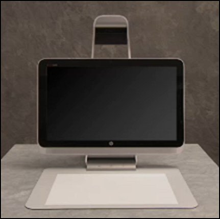
This document applies to Sprout by HP.
Avertissement :Make sure the computer is disconnected from power before starting.
Attention :This product contains components that can be damaged by electrostatic discharge (ESD). To reduce the chance of ESD damage, work over a noncarpeted floor, use a static dissipative work surface (such as a conductive foam pad), and wear an ESD wrist strap connected to a grounded surface.
Attention :Procedures in this document are provided by HP for qualified service agents and as a courtesy to its customers. Servicing internal components increases the risk of damaging the computer which might not be covered under warranty. Understand the risk and refer to the product's warranty before attempting to service the computer.
Remarque :For best quality on dial-up connections, wait until the video has fully loaded before viewing.

|
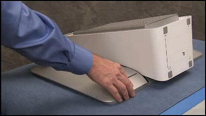
Step 1
First, remove the touch mat.
Grasp the mat with both hands and pull out from its docking location.
|

|
|
Step 2
Place the Sprout face down on a soft flat surface with the top projector of the computer overhanging the edge of the table.
|
|
|
Step 3
Remove the right and left rear covers.
To remove the covers, remove the two Philips #2 security screws at the bottom edge of the cover if they are installed on the computer.
Remarque : |

|
|
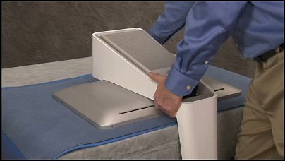
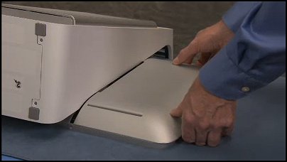
Step 4
Press your hands flat on the left rear cover and slide the cover out to the side and lift the cover off.
|
|
|
Step 5
Press your hands flat on the right rear cover and slide the cover out to the side and lift the cover off.
|

|
|
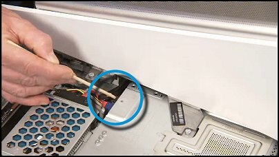
Step 6
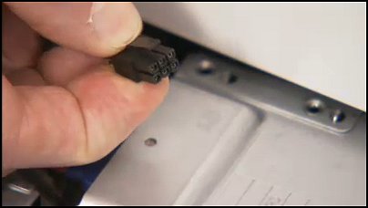
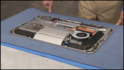
Find the black power supply connector attached to the motherboard...
|
|
|
...and detach the black power supply connector from the motherboard. The connector has a latch that must be squeezed to disconnect the connector.
|
|
|
Step 7
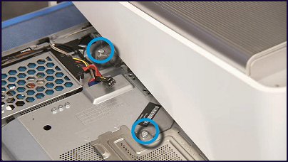
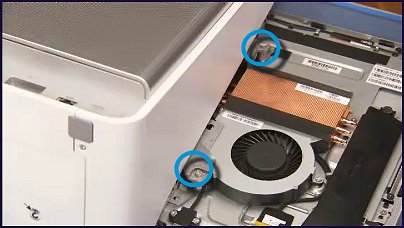
Detach the four torx head screws that secure the column to the rest of the computer, two on each side of the column.
|
|
|
Step 8
Pull the column assembly off of the computer.
|

|
|
Step 9
Find the top rear cover.
|

|
|
Step 10
Pry loose the top edge of the top rear cover...
|
|
|
...and lift and remove it from the computer.
|
|
|
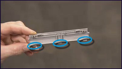
Step 1
Find the three tabs on the bottom of the top rear cover...
|
|
|
...that fit into slots on the middle frame.
|

|
|
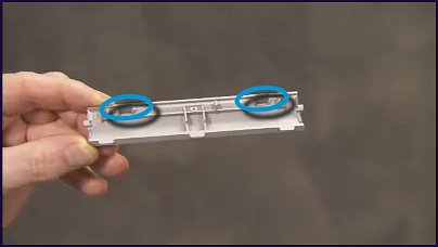
Step 2
Also find the two hooked tabs at the top of the top rear cover...
|
|
|
... that snap under spots on the back rim of the front bezel.
|

|
|
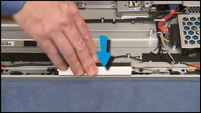
Step 3
To replace the top rear cover, first insert the bottom tabs of the cover into their slots.
|

|
|
Step 4
Press the top of the cover down until the top hooked tabs snap into place.
|
|
|
Step 5
Before replacing the column, first make sure that the rest of the computer is screen face down on a table, near enough to the edge that the top portion of the column can overhang the edge of the table when reinstalled.
|
|
|
Step 6
Find the four standoffs on the middle frame that the screws holes on the column line up with.
|

|
|
Step 7
Place the column back onto the computer, aligning the screw holes over their standoffs.
|
|
|
Step 8
Replace the four torx head screws to secure the column to the computer.
|
|
|
Step 9
Reattach the power supply connector to the motherboard.
|
|
|
Step 10
Replace the rear covers.
Place the left rear cover down onto the computer slightly to the side of its final location...
|
|
|
...and pressing your hands flat on the cover, slide it back into place.
|
|
|
Step 11
Place the right rear cover down onto the computer slightly to the side of its final location...
|
|
|
...and pressing your hands flat on the cover, slide it back into place.
|
|
|
Step 12
Replace the two Philips #2 security screw at the bottom edge of the cover if they were removed in the disassembly process.
|
|
|
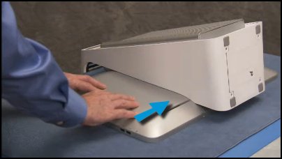
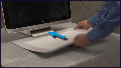
Step 13
Replace the touch mat.
Insert the connector edge of the mat into its docking port on the bottom of the computer assembly.
|
|
