solution Contentsolution Content

HP Color LaserJet Enterprise M552, M553, MFP M577, HP Color LaserJet Managed E55040, MFP E57540 - Removal and replacement: Tray 2-X paper pickup roller and separation roller assemblies

Introduction

This document provides the procedures to remove and replace the Tray 2/3/4/5 pickup, feed, and separation rollers.
Removing and Replacing Tray 2-X Paper Pickup and Separation Roller Assemblies M553
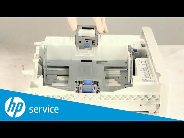
Learn how to remove and replace the tray 2-X paper pickup roller and separation roller assemblies on the HP LaserJet Enterprise M553 printer.

Before performing service
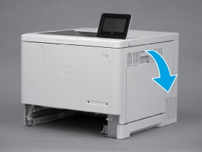
note:
The procedure in this section shows Tray 2 in the figures. However, this procedure is also correct for Tray 3, Tray 4, or Tray 5.
Turn the printer power off
  • Disconnect the power cable.
      warning:
    To avoid damage to the printer, turn the printer off, wait 30 seconds, and then remove the power cord before attempting to service the printer.
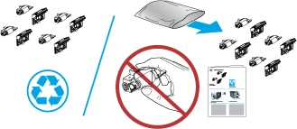
Use the table below to identify the correct part number for your printer. To order the part, go to www.hp.com/buy/parts.
Tray 2 - X pickup, feed, and separation rollers kit part number
B5L24-67904
Tray 2 - X pickup and feed rollers with instruction guide

Required tools

No special tools are required to install this part.

After performing service

Make sure that Tray 2 or Tray 3 cassette is fully closed after replacing the rollers.
Turn the printer power on
  • Connect the power cable.
  • Use the power switch to turn the power on.

Post service test

Step 1: Remove the Tray 2-X paper pickup roller assembly

note:
The procedure in this section shows Tray 2 in the figures. However, this procedure is also correct for Tray 3, Tray 4, or Tray 5.
  1. Pull the tray out until it stops.
    Figure : Pull the tray out
  2. Lift the front of the tray, and then pull it out of the printer to remove it.
    Figure : Remove the tray
  3. Open the right door.
    Figure : Open the right door
  4. Carefully raise the transfer roller assembly up and into the printer.
    Figure : Raise the transfer roller assembly
  5. Release the green handle (callout 1), and then lower the paper guide (callout 2).
    Figure : Lower the paper guide
  6. Locate the tray pickup roller assembly.
    Figure : Locate the tray pickup roller
  7. Slide the assembly to the left to compress the spring loaded shaft (callout 1), and then rotate the right end of the assembly down and away from the printer (callout 2).
    note:
    It might be easier to access the roller through the tray cavity, while viewing it through the right door opening.
    Figure : Slide the assembly to the left
  8. Remove the roller assembly.
    Figure : Remove the roller assembly

Step 2: Remove the Tray 2-X separation roller

  1. Locate the tray separation roller.
    Figure : Locate the roller assembly
  2. Push up on the blue label to release the roller assembly.
    Figure : Push up on the blue label
  3. Slide the roller assembly straight up to remove it.
    Figure : Remove the roller assembly

Step 3: Unpack the replacement rollers

Unpack the replacement assemblies from the packaging.
  caution:
Avoid touching the surface of the replacement rollers. Skin oils on the rollers can cause print-quality problems. Thoroughly wash your hands with soap and water to remove skin oils, and then completely dry them.
note:
HP recommends responsible disposal of the defective assemblies.
Figure : Recycle and unpack illustration

Step 4: Install the Tray 2-X separation roller

  1. Slide the roller assembly straight into the tray to install it.
    Figure : Install the roller assembly
  2. Make sure that the roller assembly is fully seated.
    Figure : Fully seat the roller assembly
  3. Verify that the roller assembly is correctly installed—it should be firmly attached to the tray.
    Figure : Check the installation

Step 5: Install the Tray 2-X paper pickup roller assembly

  1. Before proceeding, take note of the mounting tab (callout 1) on the replacement roller assembly.
    note:
    When correctly installed, a black-plastic protrusion in the printer fits into this tab to hold the roller in the upright position.
    Figure : Note of the mounting tab
  2. Position the roller assembly in the printer with the spring loaded shaft compressed.
    note:
    It might be easier to access the roller through the tray cavity, while viewing it through the right door opening.
    Figure : Position the roller assembly in the printer
  3. Carefully release the spring loaded shaft (callout 1) with the roller in place. The collar (callout 2) on the assembly fits over the bushing (callout 3) in the printer.
    Figure : Release the spring loaded shaft
  4. Make sure that the roller assembly is correctly installed. It must not hang down into the tray cavity. If the roller hangs down into the tray cavity, remove it, and then reinstall it.
      caution:
    If the roller assembly is not correctly installed, it will be damaged when the tray is installed.
    Figure : Verify the roller installation
  5. Close the right door.
    With the front of the tray slightly lifted, align the sides of the tray with the rails in the printer, and then carefully slide the tray into the printer.
    note:
    As the tray slides into the printer, lower the front of it.
    Figure : Install the tray
  6. Close the tray.
    Figure : Close the tray