The service station of the FB500 and FB700 employs a basin, also referred to as a tray, which temporarily accumulates fluids expelled by printhead maintenance activity. This basin has a float sensor that is lifted up when the accumulated fluid reaches a certain volume. When the float goes up, it opens a switch that causes the message W-IS-10 Waste Ink Container Full or Disconnected to be displayed on the printer's control panel. When this message is observed, the printer operator should open the drain spigot located on inside surface of the service end of the printer frame and drain the accumulated ink into an approved container for disposal in accordance with local regulations. Refer to chapter 9 of the printer user guide for detailed instructions concerning the drain spigot.
After draining the accumulated fluid and re-closing the spigot, the float in the basin will drop back down and the switch will close, causing the message to clear. If the Warning W-IS-10 message is neglected for too long, it changes to the Action A-IS-219, which requires the basin to be drained before the printer can resume normal operation.
In some instances after draining the accumulated fluid and closing the spigot, the
W-IS-10 or
A-IS-219 message continues to be displayed. This typically occurs when the float becomes stuck and fails to drop back down after the fluid is drained. If this occurs, perform the following:
1. Remove the service-end endcap enclosure for full access to the service station.
2. Tap repeatedly on the bottom of the service station basin with the handle-end of a screwdriver or similar tool. This action may free the float from the stuck position and allow it to drop, thereby closing the switch and causing the
W-IS-10 or
A-IS-219 message to clear.
3. Reinstall the endcap enclosure and resume normal operation of the printer.
Figure 1 shows a cutaway view of the service station tray to provide the approximate location of the float sensor.
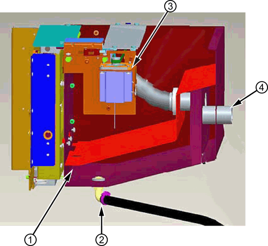
Figure 1 Cutaway view of the service station basin to show approximate location of the float sensor. This view is from the input side of the printer. Other items are identified for orientation only; they are not relevant to the specific procedure involving the float sensor.
1 - Float sensor location
2 - Waste fluid drain hose
3 - Wiper motor
4 - Air hose to service station vacuum
If this occurs repeatedly, the float sensor may require replacement to avoid future disruptions. Use the below given link to obtain a replacement sensor:
Click here to view the spare part number for "Float switch assembly".
This spare part is common to the FB500, FB700, and FB950. Figure 2 shows the float sensor assembly.
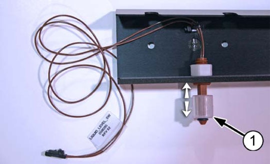
Figure 2 Float sensor assembly spare part, showing sensor and related bracket and cabling
1 - Float sensor
The float sensor switch is a normally-closed switch. This means that when the float is down, the switch is closed to complete the circuit with the printer's electronics. In a situation where the float is stuck in the up position and cannot be freed, or some other scenario where the basin is known to be empty but the switch remains open and the
W-IS-10 or
A-IS-219 message will not clear, the switch can be disconnected from the wiring harness and the harness-end connector can be jumpered temporarily. The jumper creates the same closed-circuit condition that a functional switch normally does. This configuration should be used only until a replacement, functioning float sensor assembly can be obtained (see part number provided above).
NOTE:In the absence of a functioning float sensor, waste fluids may accumulate in the service station basin beyond its intended capacity. This may result in leakage of fluid out of the basin or other undesirable consequences, including damage to other printer components. Do not operate the printer without a functioning float sensor for any longer than the time necessary to obtain a replacement.
NOTE:Do not operate the printer with the service station drain spigot in the open position. The service station requires the spigot to be closed in order to operate as designed. Leaving the drain spigot open disrupts air flow in the service station and will result in fluid accumulating in unintended locations, which may lead to leakage of waste or other undesirable consequences, including damage to other printer components. Figure 3 shows the appearance of the drain spigot when closed and when fully opened. Any other position is partially open as well.
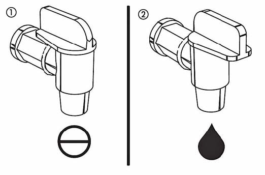
Figure 3 Service station spigot positions
1 - Closed for normal operation
2 - Open to drain liquid waste.
Any other position is partially open as well. The printer should not be operated with the spigot open or partially open.
