This document applies to HP OMEN 880 Gaming PCs.
warning:Make sure the computer is disconnected from power before starting. Before starting, power off the computer and wait for components to cool before starting these procedures.
caution:This product contains components that can be damaged by electrostatic discharge (ESD). To reduce the chance of ESD damage, work over a non-carpeted floor, use a static dissipative work surface (such as a conductive foam pad), and wear an ESD wrist strap connected to a grounded surface.
caution:Procedures in this document are provided by HP for qualified service agents and as a courtesy to its customers. Servicing internal components increases the risk of damaging the computer which might not be covered under warranty. Understand the risk and refer to the product's warranty before attempting to service the computer.

|
Step 1
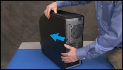
Remove the left side cover.
For detailed instructions, see Remove and Replace the Left Side Cover on the HP OMEN 880 Gaming PC.
|
|
|
Step 2
Remove the right side cover.
For detailed instructions, see Remove and Replace the Right Side Cover on the HP OMEN 880 Gaming PC.
|
|
|
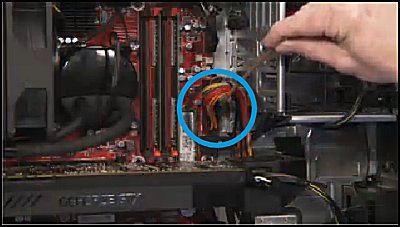
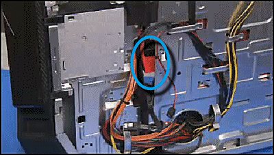
Step 3
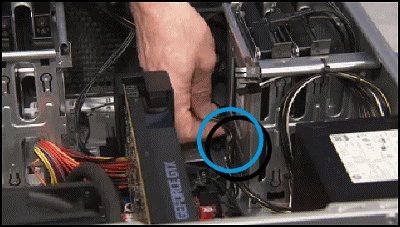
Detach the two power supply connectors from the top corner of the motherboard.
|

|
|
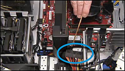
Step 4
Detach the large power supply connector from the center of the motherboard.
|
|
|
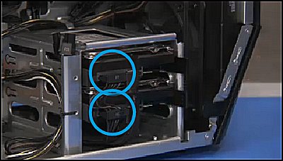
Step 5
Detach the power connector or connectors from all internal hard drives.
|
|
|
Step 6
In models with an upper internal hard drive cage, pull the upper hard drive power connectors out of the cable guides on the bottom of the upper cage.
|
|
|
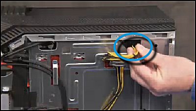
Step 7
In computers with an upper external hard drive bay, find and detach the power supply junction cables to the external hard drive power cables.
|
|
|
Step 8
Detach the power connector or connectors from the graphics card or cards installed in the unit.
|
|
|
Step 9
Remove the graphics card power cables from the cable guide on the top of the bottom internal hard drive cage.
|

|
|
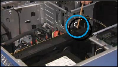
Step 10
Snip the zip tie securing the graphics power cables to the side of the bottom internal drive cage.
|
|
|
Step 11
Detach the hard drive SATA data cables from the motherboard that connect near the large motherboard power supply connector to allow the large power supply cable to be pulled to the right side of the unit.
|
|
|
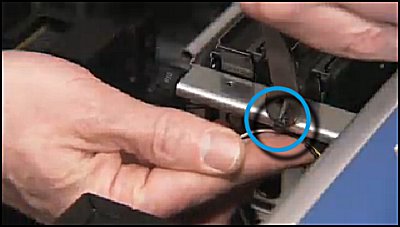
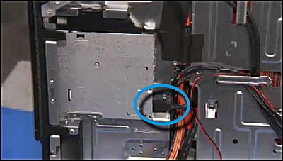
Step 12
Detach the optical drive power connector from the optical drive on the right side of the unit.
|
|
|
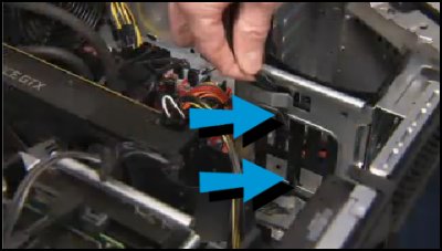
Step 13
Pull the top motherboard power supply cables to the right side of the unit through their cable access hole.
|
|
|
Step 14
Detach the optical drive data connector from the optical drive if an optical drive is installed for access for the large power supply connector.
|
|
|
Step 15
Detach the large red USB connector from the motherboard to make room for the large power supply connector if there is a long graphics card installed.
|
|
|
Step 16
Pull the large motherboard power supply connector to the right side of the computer through the central cable access hole.
|
|
|
Step 17
Pull the upper hard drive bay power cables to the right side of the unit through the central access hole.
|
|
|
Step 18
Pull the bottom internal hard drive power cables to the right side of the unit through their bottom access hole.
|

|
|
Step 19
Pull the top motherboard power supply cables out of their cable guides on the right side of the unit that lead to the bottom of the unit.
|
|
|
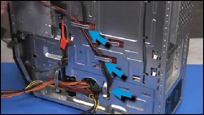
Step 20
Pull the optical drive and upper hard drive power connectors out of their cable guides on the right side. Be careful of the top I/O connectors that share the same guides.
|
|
|
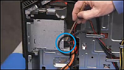
Step 21
Pull the large motherboard power cable out of its cable guide at the bottom right side of the unit.
|
|
|
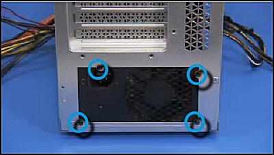
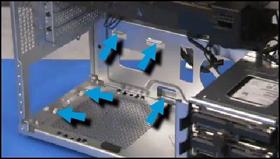
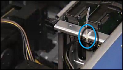
Step 22
Detach the four Philips #2 screws that secure the power supply to the rear of the computer.
|
|
|
Step 23
Slide the power supply slightly to the inside of the computer...
|
|
|
...then pull the power supply out and carefully feed the power supply connectors through the bottom access hole from the right to the left inside part of the unit to fully remove the power supply.
|
|
|
Step 1
There are guides on the inside chassis wall to assist in correct placement of the power supply.
|
|
|
Step 2
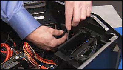
To replace the power supply, first feed the power supply connectors from the left to the right side of the computer through their bottom access hole.
|

|
|
Step 3
Align the power supply within its guides, then slide the power supply to the rear of the computer.
|
|
|
Step 4
Secure the power supply to the rear of the unit with its four Philips #2 screws
|
|
|
Step 5
Replace the large motherboard power supply connector into its large cable guide at the bottom right side of the unit.
|

|
|
Step 6
Replace the optical drive and upper hard drive power connectors into their cable guides on the right side of the computer.
note: |
|
|
Step 7
Replace the top motherboard power cables into their guides leading to the top right side of the computer.
|

|
|
Step 8
Feed the bottom internal hard drive power connectors back to the main cavity of the unit through their bottom access hole.
|
|
|
Step 9
Feed the upper hard drive power connectors back to the main cavity of the unit through the central access hole.
|
|
|
Step 10
Feed the large central motherboard power supply connector back to the main cavity through the central access hole.
|
|
|
Step 11
Replace the red USB connector to the motherboard if it was detached to make room for the large power supply motherboard connector.
|
|
|
Step 12
Replace the optical drive data connector if it was detached from the optical drive.
|
|
|
Step 13
Feed the top motherboard power supply connectors back to the main cavity of the computer through their access hole.
|
|
|
Step 14
Replace the power connector to the optical drive if an optical drive is installed in the unit.
|
|
|
Step 15
Replace the hard drive SATA connectors to the motherboard near the large power connector header.
|
|
|
Step 16
Secure the graphics card power cables to the side of the bottom internal hard drive cage with a zip tie.
|
|
|
Step 17
Place the graphics card power cables into the cable guide on the top of the bottom internal hard drive cage.
|
|
|
Step 18
Reconnect the graphics card cables to the graphics card or cards.
|
|
|
Step 19
If the unit has an upper external hard drive cage, reconnect the power junction cables to the external hard drive power cables.
|
|
|
Step 20
If the unit has an upper internal hard drive cage, place the upper hard drive power cables into the cable guides on the upper hard drive cage.
|

|
|
Step 21
Replace all connectors to all internal hard drives.
|
|
|
Step 22
Replace the large power supply connector to the motherboard.
|
|
|
Step 23
Replace the two smaller motherboard power supply connectors at the top edge of the motherboard.
|
|
|
Step 24
Replace the right side cover.
For detailed instructions, see Remove and Replace the Right Side Cover on the HP OMEN 880 Gaming PC.
|
|
|
Step 25
Replace the left side cover.
For detailed instructions, see Remove and Replace the Left Side Cover on the HP OMEN 880 Gaming PC.
|
|
