This document applies to HP Pavilion 15-abXXX notebook computers.

warning:Make sure the computer is disconnected from power before starting. Before starting, power off the computer and wait for components to cool before starting these procedures.
caution:This product contains components that can be damaged by electrostatic discharge (ESD). To reduce the chance of ESD damage, work over a non-carpeted floor, use a static dissipative work surface (such as a conductive foam pad), and wear an ESD wrist strap connected to a grounded surface.
caution:Procedures in this document are provided by HP for qualified service agents and as a courtesy to its customers. Servicing internal components increases the risk of damaging the computer which might not be covered under warranty. Understand the risk and refer to the product's warranty before attempting to service the computer.

note:The video and graphics in this article depict a specific configuration of notebook computer. These same removal and replacement procedures apply to all configurations of HP Pavilion 15-abXXX notebook computers.
|
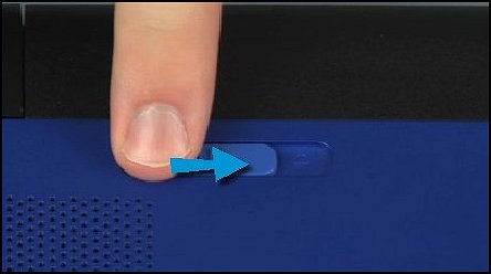
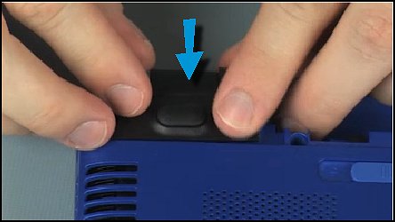
Step 1
Find the battery lock latch identified by the lock icon on the bottom of the computer and slide it to the unlock position.
|
|
|
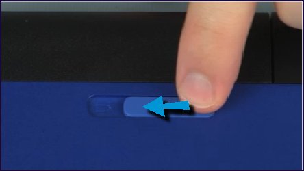
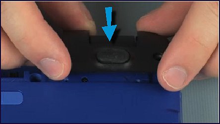
Step 2
Find the battery release latch identified by the battery icon and slide the battery release latch to the release position to partially eject the battery.
|
|
|
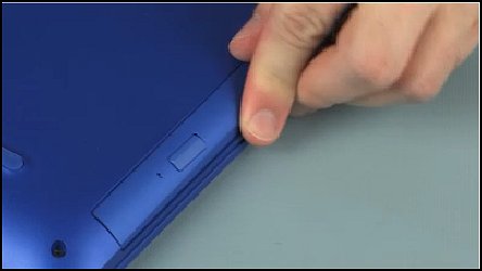
Step 3
Lift the front edge of the battery and remove the battery from the battery bay.
|

|
|
Step 4
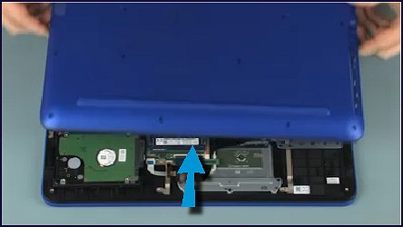
Now remove the optical drive.
Remove the 6.5 mm P1 Phillips-head screw that secures the optical drive to the base enclosure.
|

|
|
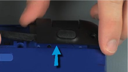
Step 5
Grasp the optical drive bezel and carefully slide the optical drive out of the base enclosure.
|
|
|
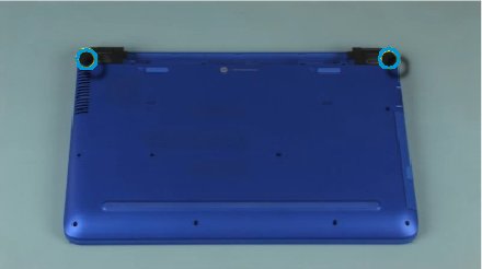
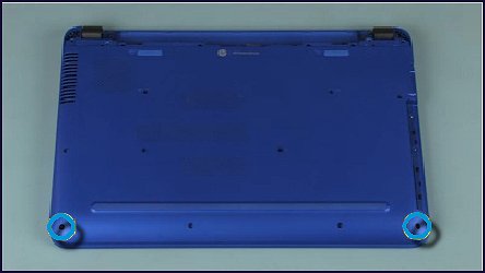
Step 6
Remove the rear corner covers
Remove the two 12 mm P1 Phillips-head screws that secure the corner covers to the base enclosure.
|
|
|
Step 7
Carefully lift the corner covers to disengage the tabs that secure them to the base enclosure and remove.
|

|
|
Step 8
Now, remove the base enclosure.
With a pair or tweezers, remove the two Mylar screw covers from the base enclosure.
|

|
|
Step 9
Remove the thirteen 6.5 mm P1 Phillips-head screws that secure the base enclosure to the top cover.
|

|
|
Step 10
Remove the two 5 mm P1 Phillips-head screws that secure the base enclosure to the top cover.
|
|
|
Step 11
Carefully separate the edges of the base enclosure from the top cover...
caution: |
|
|
... and slide it off the display panel hinges.
|
|
|
Step 1
Slide the base enclosure onto the display panel hinges.
caution: |
|
|
Step 2
Place the base enclosure into position on the top cover. Apply pressure to the edges of the base enclosure to snap it into place.
|

|
|
Step 3
Replace the two 5 mm P1 Phillips-head screws that secure the base enclosure to the top cover.
|
|
|
Step 4
Replace the thirteen 6.5 mm P1 Phillips-head screws that secure the base enclosure to the top cover.
|
|
|
Step 5
Place the two Mylar screw covers into position on the base enclosure.
|
|
|
Step 6
Align the corner covers with the base enclosure and press down on the corner covers to secure them into position.
|
|
|
Step 7
Replace the two 12 mm P1 Phillips-head screws that secure the corner covers to the base enclosure.
|
|
|
Step 8
Insert the optical drive into the optical drive bay...
|

|
|
...until the optical drive bezel is flush with the side of the base enclosure.
|
|
|
Step 9
Replace the 6.5 mm P1 Phillips-head screw that secures the optical drive to the base enclosure.
|
|
|
Step 10
Insert the rear edge of the battery into the battery bay and lower the battery until it is properly seated and the battery release latch clicks.
|

|
|
Step 11
Slide the battery lock to the lock position to secure the battery.
|

|
