This document applies to Sprout by HP.
warning:Make sure the computer is disconnected from power before starting.
caution:This product contains components that can be damaged by electrostatic discharge (ESD). To reduce the chance of ESD damage, work over a noncarpeted floor, use a static dissipative work surface (such as a conductive foam pad), and wear an ESD wrist strap connected to a grounded surface.
caution:Procedures in this document are provided by HP for qualified service agents and as a courtesy to its customers. Servicing internal components increases the risk of damaging the computer which might not be covered under warranty. Understand the risk and refer to the product's warranty before attempting to service the computer.
note:For best quality on dial-up connections, wait until the video has fully loaded before viewing.

|
Step 1
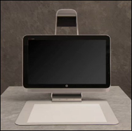
First, remove the TouchMat.
Grasp the mat with both hands and pull out from its docking location.
|

|
|
Step 2
Place the Sprout face down on a soft flat surface with the top projector of the computer overhanging the edge of the table.
|

|
|
Step 3
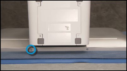
Remove the Philips #2 security screw at the bottom edge of the cover if the screw is installed in the computer.
note: |
|
|
Step 4
Press your hands flat on the right rear cover and slide the cover out to the side and lift the cover off.
|

|
|
Step 5
Pull the memory EMI shield off of the motherboard EMI shield.
|

|
|
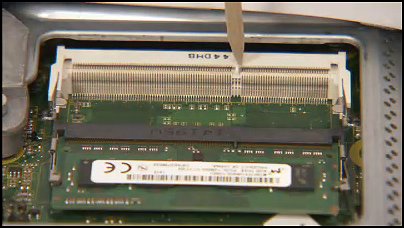
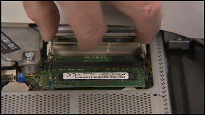
Step 6
Next, gently pull out on the retaining lever located on each side of the SO-DIMM memory module. The module pops up from its socket.
|
|
|
Step 7
Grasp the memory module by the edges and pull the module out of the socket.
Place the memory module in a static dissipative bag to protect it from electrostatic discharge.
|

|
|
Step 1
Find the small notch on one side of each SO-DIMM module...
|

|
|
...that fits over a small tab on one side of each SO-DIMM socket.
|
|
|
Step 2
To replace an SO-DIMM memory module, angle the module to about 30 degrees, engaging the notch into its socket tab.
|
|
|
Step 3
Press the module down into place until the retaining levers snap into position over the sides of the module.
|

|
|
Step 4
Carefully align the bottom edge of the EMI shield over the memory slot cutout on the motherboard shield – then press it down into place.
|

|
|
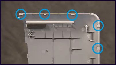
Step 5
Find the tabs on the side, top, and bottom of the cover...
|
|
|
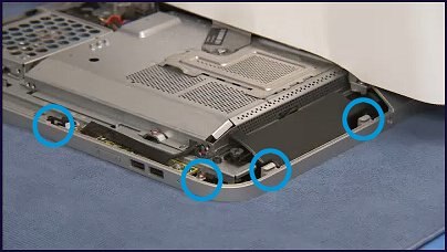
...and the slots on the side, top, and bottom of the computer case.
|
|
|
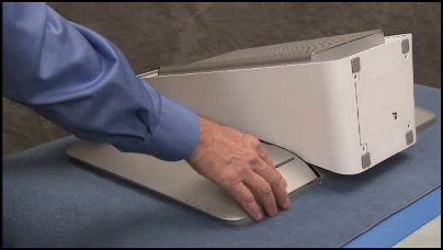
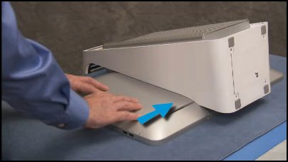
Step 6
Place the cover down onto the computer slightly to the side of its final location...
|
|
|
...and pressing your hands flat on the cover, slide it back into place.
|
|
|
Step 7
Replace the Philips #2 security screw at the bottom edge of the cover if it was removed in the disassembly process.
|
|
|
Step 8
Replace the TouchMat.
Insert the connector edge of the mat into its docking port on the bottom of the computer.
|

|
