Introduction
The following information provides the procedures to install or replace a stapler/stacker accessory for the HP LaserJet Enterprise M806 and HP LaserJet Enterprise flow MFP M830.
note:To see a short video demonstrating this procedure, click here.
Before you begin
Use the following table to identify the correct accessory part number for the accessory, and then go to www.hp.com/buy/parts to order the accessory.
|
CZ994A
|
Stapler/stacker accessory with installation instructions
|
|
CZ995A
|
Stapler/stacker with 2/3 hole punch accessory with installation instructions
|
|
CZ996A
|
Stapler/stacker with 2/4 hole punch accessory with installation instructions
|
To replace an existing stapler/stacker, go to Step one: Remove the stapler/stacker.
To install a new stapler/stacker, go to Step three: Install the optional or replacement stapler/stacker accessory.
Required tools
No special tools are required to install this accessory.
Step one: Remove the stapler/stacker
note:If the product does not have a stapler/stacker installed and you are installing an optional stapler/stacker, go to Step three: Install the optional or replacement stapler/stacker accessory.
-
Turn off the product, and then disconnect the power cord.
caution:
Turn the product off, wait five seconds, and then remove the power cord before attempting to service the product. -
At the back of the product, disconnect the finishing accessory interface cable.Figure : Disconnect the accessory cable

-
Open the finishing accessory front cover. Release and hold the bottom handle first, and then release and hold the top handle. Hold both handles at the same time, and then slide the finishing accessory away from the product.
caution:
Failure to follow these instructions might damage the product.Figure : Release the finisher
-
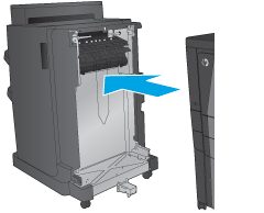
Completely remove the finishing accessory.Figure : Remove the finishing accessory
Step two: Unpack the optional or replacement stapler/stacker accessory
Unpack the stapler/stacker from the packaging.
note:Remove all tape and packing material from outside the accessory. Open all doors and remove all tape and packing material from inside the product.
For recycling information, go to www8.hp.com/us/en/hp-information/environment/product-recycling.html.
note:HP recommends responsible disposal of the defective stapler/stacker.
-
Remove all of the shipping tape from outside the accessory.Figure : Remove the shipping tape

-
Open the front door of the accessory, and then remove all of the shipping tape and packing materials from inside the accessoryClose the front door.
caution:
Make sure that you remove all of the shipping material from inside the accessory.Figure : Remove the shipping tape and packing materials
Step three: Install the optional or replacement stapler/stacker accessory
-
If you have not already done so, turn off the product and disconnect the power cord.
caution:
Turn the product off, wait five seconds, and then remove the power cord before attempting to service the product. -
Attach the accessory to the product.Figure : Attach the accessory

-
Use the adjustment wheels on the accessory to align that accessory with the edge of the product.
note:
If the accessory is not correctly aligned with the product, you might experience excessive paper jams.Figure : Align the accessory and the product
-
If you are installing an optional accessory for the first time, at the back of the product remove the accessory interface cable cover.Figure : Remove the accessory cable cover

-
Connect the finishing accessory interface cable.Figure : Connect the accessory interface cable

-
Connect the product power cord, and then turn on the product.
Step four: Parts return
The following URL provides information on how to return parts to HP for reuse and recycling: Product return and recycling
note:HP recommends responsible disposal of the defective stapler/stacker.
Step five: Configure the default hole punch location
-
From the Home screen on the product control panel, scroll to and touch the Administration button.
-
Open the following menus:
-
Stapler/Stacker Settings
-
Hole Punching
-
-
Select a hole punch location from the list of options, and then touch the Save button. The following hole punch options are available for either a 2/3 Hole Puncher or 2/4 Hole Puncher:Hole punch location2/3 Hole Puncher2/4 Hole PuncherNone
 Two left or top
Two left
Two right
Two top
Two bottom
Three left
Three top
Three right
Three top
Three left or top
Four left
Four right
Four top
Four left or top
Two left or top
Two left
Two right
Two top
Two bottom
Three left
Three top
Three right
Three top
Three left or top
Four left
Four right
Four top
Four left or top
note:
Not all options are available. Available options depend on whether the hole punch accessory is a 2/3 or 2/4 hole puncher.
note:To use the hole puncher, load Letter or A4-size paper with the long edge of the paper along the right edge of the tray (long-edge feed).
Step six: Configure the default staple location
-
From the Home screen on the product control panel, scroll to and touch the Administration button.
-
Open the following menus:
-
Stapler/Stacker Settings
-
Stapling
-
-
Select a staple location from the list of options, and then touch the Save button. The following staple options are available:
-
None
-
Top left
-
Top right
-
Two left
-
Two right
-
Two top
-
Two top or left
-


 button to display the IP address or host name.


