solution Contentsolution Content

HP ZR22w and ZR24w LCD Monitors - Setting Up the Monitor

To set up the monitor, ensure that the power is turned off to the monitor, computer system, and other attached devices, then follow the instructions below.
note:
Be sure the master power switch, located on the rear panel of the monitor, is in the off position. The master power switch turns off all power to the monitor.

Installing the Monitor Pedestal Base

note:
Do not install the pedestal base if the monitor will be used on a wall, swing arm, or other mounting fixture; instead see Mounting the Monitor in this chapter.
  1. Using both hands, position the monitor over the pedestal base.
      caution:
    Do not touch the surface of the LCD panel. Pressure on the panel may cause non-uniformity of color or disorientation of the liquid crystals. If this occurs the screen will not recover to its normal condition.
  2. Press down firmly on the monitor to lock the pedestal base in place. When the base locks, it will make a clicking sound.
    Figure :
note:
Be sure the pedestal base is securely locked before continuing with the setup.

Rear Components

HP ZR22w and ZR24w Models

Figure :
Rear Components
Component
Function
1
Cable Lock Provision
Provides slot for use with cable security locks.
2
Master Power Switch
Turns off all power to the monitor.
3
AC Power Connector
Connects the AC power cord to the monitor.
4
DisplayPort Connector
Connects the DisplayPort cable to the monitor.
5
DVI-D Connector
Connects the DVI-D cable to the monitor.
6
VGA Connector
Connects the VGA cable to the monitor.
7
USB Upstream Connector
Connects the monitor USB hub cable to a host USB port/hub.
8
USB Downstream Connectors
Connects optional USB devices to the monitor.
9
USB Downstream Connectors (side panel)
Connects optional USB devices to the monitor.

Routing and Connecting the Cables

  1. Place the monitor in a convenient, well-ventilated location near the computer.
  2. Remove the cable routing cover by pulling it straight off the front of the column.
    Figure :
  3. Before connecting the cables, route them through the cable routing hole in the column (1) and replace the cable routing cover (2).
    Figure :
  4. Connect a VGA signal cable, DVI-D signal cable, or DisplayPort signal cable.
    note:
    The monitor is capable of supporting either analog or digital input. The video mode is determined by the video cable used. The monitor will automatically determine which inputs have valid video signals. The inputs can be selected by pressing the +/Source button on the front panel or through the On-Screen Display (OSD) feature by pressing the Menu button.
    • For analog operation, use the VGA signal cable provided. Connect the VGA signal cable to the VGA connector on the rear of the monitor and the other end to the VGA connector on the computer.
    • For DVI digital operation, use the DVI-D signal cable provided. Connect the DVI-D signal cable to the DVI connector on the rear of the monitor and the other end to the DVI connector on the computer.
    • For DisplayPort digital operation, use the DisplayPort signal cable provided. Connect the DisplayPort signal cable to the DisplayPort connector on the rear of the monitor and the other end to the DisplayPort connector on the computer.
  5. Connect one end of the provided USB cable to the USB hub connector on the rear panel of the computer, and the other end to the upstream USB connector on the monitor.
  6. Connect one end of the power cable to the AC power connector on the back of the monitor, and the other end to an electrical wall outlet.
    Figure :
  warning:
To reduce the risk of electric shock or damage to the equipment:
Do not disable the power cord grounding plug. The grounding plug is an important safety feature.
Plug the power cord into a grounded (earthed) electrical outlet that is easily accessible at all times.
Disconnect power from the equipment by unplugging the power cord from the electrical outlet.
For your safety, do not place anything on power cords or cables. Arrange them so that no one may accidentally step on or trip over them. Do not pull on a cord or cable. When unplugging from the electrical outlet, grasp the cord by the plug.

Connecting USB Devices

The monitor provides USB connectors on the side panel and on the rear panel that can be used to connect devices such as a digital camera, USB keyboard, or USB mouse.
note:
You must connect the USB hub cable from the monitor to the computer to enable the USB 2.0 ports on the monitor. Refer to Step 5 in Routing and Connecting the Cables.
Figure :

Adjusting the Monitor

  1. Tilt the monitor's panel forward or backward to set it to a comfortable eye level.
    Figure :
  2. Swivel the monitor to the left or right for the best viewing angle.
    Figure :
  3. Adjust the monitor's height so that it is parallel to your eye height for a comfortable viewing position. A lock-down/release button on the back of the column prevents the display head from sliding up when the monitor is lifted. If the display head is locked in the lowest height position:
    1. Make sure that the monitor is safely positioned on a stable surface.
    2. Gently push down on the display head (1).
    3. While pushing down the display head, press the lock-down/release button on the back of the column (2).
    4. Guide the display head up to the desired height (3).
    Figure :
  4. Raise the monitor panel to its highest position and pivot the monitor clockwise from landscape to portrait orientation viewing to adapt to your application.
    note:
    It may be necessary to tilt the monitor panel back to prevent the corner of the panel from coming in contact with the base when pivoting.
    Figure :
    note:
    To view information on the screen in portrait mode, you will need to install the Pivot Pro software included on the software and documentation CD. The position of the OSD menu can also be rotated to portrait mode. To rotate the OSD menu, press the Menu button on the monitor's front panel, then select OSD Control > Rotate OSD.

Turning on the Monitor

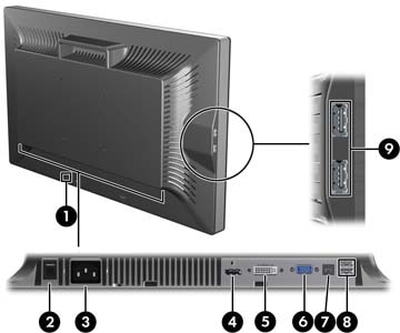
  1. Ensure that the master power switch on the rear of the monitor is in the On position.
  2. Press the power button on the computer to turn it on.
  3. Press the power button on the front of the monitor to turn it on.
  caution:
Burn-in image damage may occur on monitors that display the same static image on screen for a prolonged period of time.* To avoid burn-in image damage on the monitor screen, you should always activate a screen saver application or turn off the monitor when it is not in use for a prolonged period of time. Image retention is a condition that may occur on all LCD screens. Monitors with a “burned-in image” are not covered under the HP warranty.
* A prolonged period of time is 12 consecutive hours of non-use.
note:
If pressing the power button has no effect, the Power Button Lockout feature may be enabled. To disable this feature, press and hold the monitor power button for 10 seconds.
note:
You can disable the power LED in the OSD menu. Press the Menu button on the front of the monitor, then select Management > Bezel Power LED > Off.
When the monitor is powered on, a Monitor Status message is displayed for five seconds. The message shows which input (DisplayPort, DVI, or VGA) is the current active signal, the status of the auto-switch source setting (On or Off; factory default is On), the default source signal (factory default is DisplayPort), the current preset display resolution, and the recommended preset display resolution.
The monitor automatically scans the signal inputs for an active input and uses that input for the display. If two or more inputs are active, the monitor will display the default input source. If the default source is not one of the active inputs, then the monitor will display the highest ranking priority input in the following order: DisplayPort, DVI, then VGA. You can change the default source in the OSD by pressing the front panel menu button and selecting Source Control > Default Source.

Removing the Monitor Pedestal Base

You can remove the monitor panel from the pedestal base to mount the panel on a wall, a swing arm, or other mounting fixture (purchased separately).
This monitor has a Quick Release mechanism that allows you to easily remove and replace the monitor panel to the pedestal base.
  caution:
Before beginning to disassemble the monitor, be sure the monitor is turned off and the power and signal cables are both disconnected. Also disconnect any USB cables that are connected to the monitor.
  1. Disconnect and remove the signal and power cables from the back of the monitor.
  2. Slide the quick release latch (1) on the pedestal base to the side (either right or left).
  3. Pull up on the monitor display head (2) to remove it from the base.
    Figure :

Mounting the Monitor

note:
This apparatus is intended to be supported by UL or CSA Listed wall mount bracket.
The HP Quick Release can be removed from the pedestal base and installed to a mounting fixture. It allows you to quickly and securely attach the monitor panel to the mounting fixture.
  1. Remove the monitor panel from the pedestal base. Refer to Removing the Monitor Pedestal Base in the previous section.
      caution:
    This monitor supports the VESA industry standard 100 mm mounting holes. To attach a third-party mounting solution to the monitor, four 4 mm, 0.7 pitch, and 10 mm long screws are required (not provided with the monitor). Longer screws must not be used because they may damage the monitor. It is important to verify that the manufacturer’s mounting solution is compliant with the VESA standard and is rated to support the weight of the monitor display panel. For best performance, it is important to use the power and video cables provided with the monitor.
  2. Remove the Quick Release from the pedestal base by removing the four screws.
    Figure :
  3. Mount the Quick Release to a swing arm or other mounting fixture using the four screws removed from the Quick Release in the previous step.
    Figure :
      caution:
    The Quick Release can also be installed directly to a wall to mount the monitor panel. It is designed to support a maximum of up to 10.9 kg (24 lbs). If you are mounting to a wall, HP recommends that you consult with a qualified engineering, architectural, or construction professional to determine the appropriate type and quantity of mounting fasteners required for your application and to ensure that the mounting solution is properly installed to support applied loads.
  4. Insert the monitor panel into the Quick Release, and then press down firmly on the monitor to lock it in place. When the Quick Release locks, it will make a clicking sound.
    Figure :

Locating the Rating Labels

The rating labels on the monitor provide the spare part number, product number, and serial number. You may need these numbers when contacting HP about the monitor model. The rating labels are located on the rear panel of the monitor display head.
Figure :

Installing a Cable Lock

You can secure the monitor to a fixed object with an optional cable lock available from HP.