solution Contentsolution Content

HP Color LaserJet Enterprise M552, M553, MFP M577, HP Color LaserJet Managed E55040, MFP E57540 - Removal and replacement: Intermediate transfer belt (ITB) and secondary transfer roller

Introduction

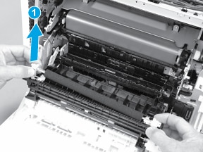
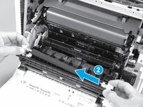
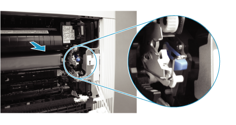
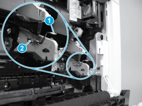
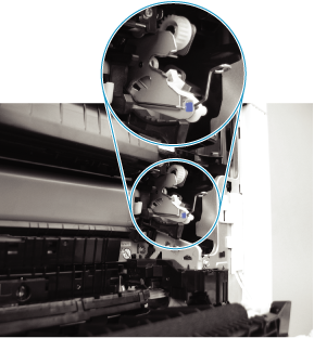
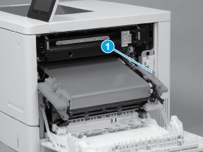
This document provides the procedures to remove and replace the secondary transfer roller and the intermediate transfer belt (ITB).
How to Replace the Intermediate Transfer Belt and Secondary Transfer Roller on the HP LaserJet Enterprise M553 Printer
Learn how to remove and replace the Intermediate Transfer Belt (ITB) and the Secondary Transfer Roller on the HP LaserJet Enterprise M553 printer.

Before performing service

Turn the printer power off
  • Disconnect the power cable.
      warning:
    To avoid damage to the printer, turn the printer off, wait 30 seconds, and then remove the power cord before attempting to service the printer.
Use the table below to identify the correct part number for your printer. To order the part, go to www.hp.com/buy/parts.
Secondary transfer roller kit part number
B5L24-67901
Secondary transfer roller and intermediate transfer belt (ITB) with instruction guide

Required tools

No special tools are required to install this part.

After performing service

Make sure that the right door is fully closed after replacing the secondary transfer roller and ITB.
Turn the printer power on
  • Connect the power cable.
  • Use the power switch to turn the power on.

Post service test

Print a configuration page to make sure that the printer is functioning correctly.

Step 1: Remove the transfer roller

  1. Open the right door.
    Figure : Open the right door
  2. Push in on the blue lever (callout 1) to release the secondary transfer roller assembly, and then lower the assembly (callout 2) to the service position.
    Figure : Lower the secondary transfer roller assembly
  3. Slightly lift the left end of the roller shaft (callout 1; near the gear) to release the transfer roller clip.
    Figure : Release the secondary transfer roller clip
  4. Slide the right end roller collar (callout 2) to the left to remove the transfer roller.
    Figure : Remove the secondary transfer roller

Step 2: Remove the ITB

  caution:
Do not touch the grey-plastic belt. Skin oils and fingerprints on the belt can cause print-quality problems.
  1. Pull the blue lever to release the ITB drive coupling.
    Figure : Release the ITB drive coupling
  2. Release the left-side ITB spring (callout 1) from the tab (callout  2).
    Figure : Release the front-side ITB spring
  3. Place the left-side ITB spring on the holder to keep it out of the way.
    note:
    The holder is colored blue to help locate it.
    Figure : Place the spring on the holder
  4. Release the right-side ITB spring (callout 1) from the tab (callout  2).
    Figure : Release the rear-side ITB spring
  5. Place the right-side ITB spring on the holder to keep it out of the way.
    note:
    The holder is colored blue to help locate it.
    Figure : Place the spring on the holder
  6. Grasp the two blue handles on the ITB.
      caution:
    If the ITB is removed to access other assemblies in the printer, use care. The ITB is a sensitive assembly. Be careful when handling the ITB so that it is not damaged. Always place the ITB in a safe and protected location.
    Figure : Grasp the ITB handles
  7. Pull the ITB out of the printer to remove it.
      caution:
    Do not touch the grey-plastic belt. Skin oils and fingerprints on the belt can cause print-quality problems.
    Figure : Remove the ITB

Step 3: Unpack the replacement secondary transfer roller and ITB

Unpack the replacement assembly from the packaging.
  caution:
Make sure that all of the packing materials and tape is removed from the replacement ITB. The ITB might be damaged if packing materials are in place when the printer power is turned on.
note:
HP recommends responsible disposal of the defective assemblies.
Figure : Recycle and unpack illustration

Step 4: Install the transfer roller

  1. Install the right end (callout 1; near the white collar) of the roller assembly in the printer.
    Figure : Install the secondary transfer roller right end
  2. Rotate the left end (the gear end) down (callout 1) to install it.
    note:
    Make sure that both ends of the roller assembly are fully seated in the holders.
    Figure : Install the secondary transfer roller right end

Step 5: Install the ITB

  caution:
Do not touch the grey-plastic belt. Skin oils and fingerprints on the belt can cause print-quality problems.
  1. Hold the ITB by the orange handles.
    Figure : Handle the ITB by the edges
  2. Align the ITB with the slots in the printer, and then carefully push it into the printer.
    note:
    Be careful. Do not dislodge the ITB retainer springs from the holders on the chassis. The springs can interfere with installing the ITB.
    Figure : Align the ITB with the slots in the product
  3. Continue to carefully push the ITB into the printer until it the orange handles stop it.
    Figure : Orange handles stop
  4. Release one tab (callout 1).
    Figure : Release one tab
  5. Remove the orange handle. Repeat this step for the remaining orange handle.
    note:
    HP recommends recycling the plastic handles.
    Figure : Remove the orange handle
  6. Continue to carefully push the ITB into the printer until it is fully installed.
    Figure : Install the ITB
  7. Remove the right-side ITB spring from the holder.
    Figure : Remove the spring from the holder
  8. Fasten the right-side ITB spring (callout 1) under the tab (callout  2).
    Figure : Fasten the rear-side ITB spring
  9. Remove the left-side ITB spring from the holder.
    Figure : Remove the spring from the holder
  10. Fasten the left-side ITB spring (callout 1) under the tab (callout  2).
    Figure : Fasten the front-side ITB spring
  11. Push in the blue lever to engage the ITB drive coupling.
    note:
    If the ITB drive coupling is not fully engaged, the right door will not properly close.
    Figure : Engage the ITB drive coupling
  12. Close the right door.
    note:
    The right door should close easily if the ITB assembly is correctly installed.
    Figure : Close the right door