note:The figures in this section show the M506 and M527 Tray 2. However, the procedure is correct for replacing the Tray 2 pickup and feed roller and separation roller assemblies in the M501, as well as the optional Tray 3, Tray 4, and Tray 5 accessories.The M501 only supports one optional input accessory (Tray 3).
HP LaserJet Pro M501, M506, MFP M527, HP LaserJet Managed E50045, E52545 - Removal and replacement: Tray 2-x roller kit
Introduction
This document provides the procedures to remove and replace the paper pickup and feed roller and separation roller assemblies (trays 2-x).

How to Replace the Tray 2-x Roller Kit for HP LaserJet Pro M501, Enterprise M50x, MFP/Flow M52x, Managed E50145, E52645
No audio. Learn how to replace the tray 2-x roller kit for HP LaserJet Pro M501, Enterprise M50x, MFP/Flow M52x, Managed E50145, E52645.
Before performing service
Turn the printer power off
-
Disconnect the power cable.
warning:
To avoid damage to the printer, turn the printer off, wait 30 seconds, and then remove the power cable before attempting to service the printer.
Use the table below to identify the correct part number for your printer. To order the part, go to www.hp.com/buy/parts.
|
Paper pickup and feed roller and separation roller assemblies (Tray 2-x) part number
|
|
|
J8H60-67903
RM2-5752-000CN
|
Trays 2-3 roller kit with instruction guide (M501) - parts for one tray
Trays 2-x roller kit with instruction guide (M506/M527) - parts for two trays
|
Required tools
-
No special tools are required to remove this part.
After performing service
Turn the printer power on
-
Connect the power cable.
-
Use the power switch to turn the power on.
Post service test
Make sure that the printer initializes to a Ready state.
Print a page from the tray that the roller assemblies were replaced in to make sure that the printer is functioning correctly.
Step 1: Remove the tray
-
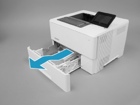
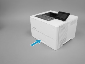
Pull the tray straight out of the printer until it stops.Figure : Pull the tray out until it stops

-
Lift the front of the tray, and then pull it out of the printer to remove it.Figure : Release and remove the tray
Step 2: Remove the pickup and feed roller assembly
caution:When handling the roller assembly, do not touch the gray spongy portion of the rollers. Skin oils on the rollers can cause paper handling problems. HP recommends washing your hands before handling the assembly.
note:The figures in this section show the M506 and M527 Tray 2. However, the procedure is correct for replacing the Tray 2 pickup and feed roller and separation roller assemblies in the M501, as well as the optional Tray 3, Tray 4, and Tray 5 accessories.
-
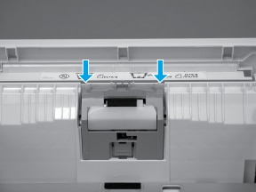
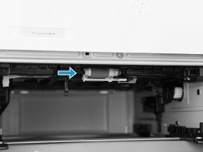
Look up into the tray cavity to locate the roller assembly.Figure : Locate the roller assembly
-
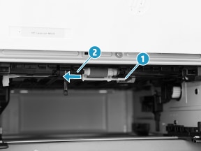
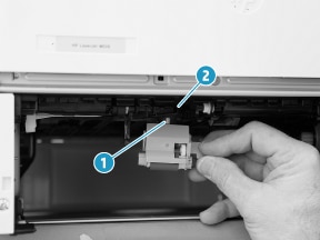
Grasp the white tab on the roller holder (callout 1), and then slide the roller assembly to the left to compress the spring loaded shaft (callout 2).Figure : Compress the spring-loaded shaft
-
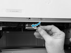
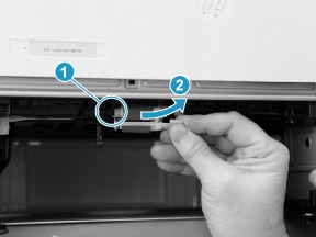
With the spring loaded shaft depressed, rotate the right side of the roller assembly down and towards you to release it.Figure : Remove the roller assembly
Step 3: Remove the separation roller assembly
-
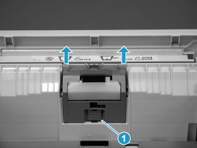
At the removed tray, release one tab (callout 1), and then pull the separation roller assembly straight up to release it.Figure : Release the assembly
-
Remove the separation roller assembly.
note:
The spring under the separation roller assembly is not captive. Do not lose the spring when removing or installing the separation pad assembly.Figure : Remove the assembly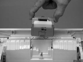
Step 4: Unpack the replacement assemblies
Unpack the replacement part from the packaging.
note:HP recommends responsible disposal of the defective part.
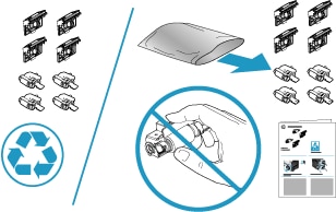
note:The number of roller assemblies in the kit depends on the specific printer kit. The figure below shows the M506/M527 kit contents. For the M501kit, only two sets of roller assemblies are supplied (one each for Tray 2 and the optional paper feeder accessory).
Recycle and unpack
Figure : Contents of J8H60-67903 - parts for one tray
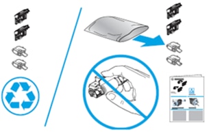
Figure : Contents of RM2-5752-000CN - parts for two trays
Step 5: Install the separation roller assembly
-
Make sure that the spring is in place (callout 1), and then install the replacement assembly in the slot in the tray.
note:
The spring under the separation roller assembly is not captive. Do not lose the spring when removing or installing the separation pad assembly.Figure : Install the assembly in the slot
-
Push the assembly straight down until the tab snaps into place.Figure : Install the assembly
-
Repeatedly push down on and then release the separation pad. If the assembly is correctly installed it should freely move up and down in the holder. If it does not move freely, remove it and then reinstall it (see step Make sure that the spring is in place (callout 1), and then install the replacement assembly in the slot in the tray.).Figure : Check the installation
Step 6: Install the pickup and feed roller assembly
caution:When handling the roller assembly, do not touch the gray spongy portion of the rollers. Skin oils on the rollers can cause paper handling problems. HP recommends washing your hands before handling the assembly.
note:The figures in this section show the M506 and M527 Tray 2. However, the procedure is correct for replacing the Tray 2 pickup and feed roller and separation roller assemblies in the M501, as well as the optional Tray 3, Tray 4, and Tray 5 accessories.
-
When the assembly is installed, the actuator pin (callout 1) on the roller assembly must be installed in the slot (callout 2) in the actuator arm.Figure : Check the pin on the assembly
-
Position the left end of the assembly on the spring loaded shaft and push it left to compress the shaft (callout 1), keep the roller holder parallel to the underside of the printer, and then rotate the right end up and into the printer (callout 2).Figure : Install the roller assembly
-
Slowly release the depressed spring loaded shaft to allow the right end of the roller assembly to engage with the right-side drive shaft.Make sure that the right side of the assembly is fully engaged with the right-side drive shaft.Figure : Decompress the spring-loaded shaft
-
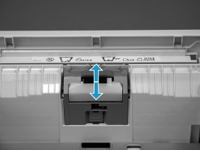
To check the installation, repeatedly push up and release, the tray actuator (callout 1) and observe the roller assembly. If the assembly is correctly installed, it moves up and down (callout 2).
note:
If the assembly does not properly move, remove it and then reinstall it, making sure that the pin on the assembly is installed in the slot in the actuator arm. See Check the pin on the assembly.Figure : Check the installation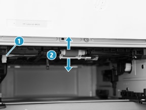
Step 7: Install the tray
-
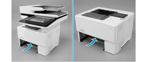
With the tray at a slight angle, align the sides of the tray with the rails in the accessory, and then partially slide the tray into the printer.Figure : Install the tray

-
Push the tray straight into the accessory to close it.Figure : Close the tray
Enter a topic to search our knowledge library
What can we help you with?

Need Help?