Figure : Display

|
Item #
|
Component
|
Description
|
|
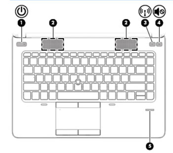
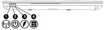
1
|
WLAN antennas (2)
|
Send and receive wireless signals to communicate with wireless
|
|
2
|
WWAN antennas (2) (select models only)
|
Send and receive wireless signals to communicate with wireless
wide area networks (WWAN).
|
|
3
|
Internal microphones (2)
|
Record sound
|
|
4
|
Webcam light
|
On: The webcam is in use
|
|
5
|
Webcam
|
Records video and captures still photographs.
|
|
6
|
Internal display switch1
|
Turns Off the display or initiates Sleep if the display is closed
while the power is On.
|
note: |
||