note:This document applies to the HP Designjet 4020 Printer series only.
HP Designjet 4020 Printer Series - Printer Assembly
Get started
The following topics describe how to assemble your new printer (also described in the Setup instructions).
Because some of the components of the printer are bulky, you may need up to four people to lift them. You will also need at least 3 × 5 m (10 × 16 ft) of empty floor space, and about two hours.
The symbols on the boxes identify the contents. Refer to the table below:
|
Symbol on box
|
Contents of box
|

|
Printer body
|

|
Stand and bin assembly
|

|
Consumables box, including ...
 Maintenance Kit (please keep this safe) Maintenance Kit (please keep this safe)
|

|
Spare box (used while attaching the stand to the printer)
|
Figure : Symbols on boxes

Unpack the printer
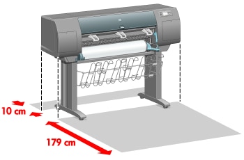
Before you start unpacking, consider where you are going to put the assembled printer. You should allow some clear space at the back and at the front of the printer. The recommended clearances are shown in the illustration below.
Figure : Clearances at the back and front of the printer
When you have identified a suitable location, you can begin unpacking.
-
Remove the two side lids. Then remove all the upper four plastic handles from both sides of the box (two each side).Figure : Removing lids and handles

-
Cut the strap around the boxes carefully, as the boxes may fall as soon as the strap is cut.Figure : Cutting the strap

-
Remove the boxes from the top of the main printer box.Figure : Removing the accessory boxes

-
Remove all eight plastic handles from both sides of the box.Figure : Removing the plastic handles

-
Remove the main printer box.Figure : Removing the main printer box

-
Remove the two packing pieces.Figure : Removing the packing pieces

Assemble the stand
warning:When you are unpacking the leg assembly, you will see that there is anti-slip material around two of the wheels on the feet. Do not remove this material yet.
-
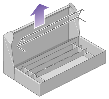
Remove the first tray from the stand and bin assembly box.Figure : Removing the first tray

-
From the first tray, remove the two boxes marked with L and R. Place them on the floor as shown.Figure : Removing the two boxes

-
Lower the cross-brace on to the L and R boxes.Figure : Lowering the cross-brace

-
You now need to identify which is the left and the right side of the cross-brace.Figure : Identifying left and right
 (1) left (2) right (3) one hole (4) two holes
 -
Now you will need the bag of screws and the screwdriver provided. You may notice that the screwdriver is slightly magnetic.Figure : Screwdriver and screws

-
Remove the two leg covers from the left leg.Figure : Left leg and leg covers

-
Lower the left leg onto the left side of the cross-brace. The left leg will fit only on the left side of the cross-brace.Figure : Lowering the left leg onto the cross-brace

-
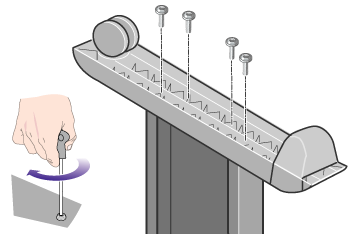
Fix the left leg to the cross-brace using four screws on the inner side of the leg.Figure : Fixing the left leg to the cross-brace (1)

-
Fix the left leg to the cross-brace using two screws on the outer side of the leg.Figure : Fixing the left leg to the cross-brace (2)

-
Lower the right leg onto the right side of the cross-brace. The right leg will fit only on the right side of the cross-brace.Figure : Lowering the right leg onto the cross-brace

-
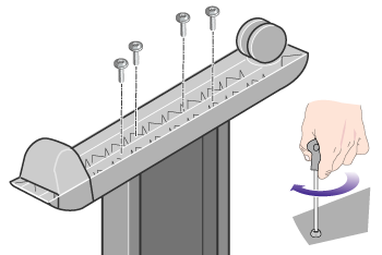
Fix the right leg to the cross-brace using four screws on the inner side of the leg.Figure : Fixing the right leg to the cross-brace (1)

-
Fix the right leg to the cross-brace using two screws on the outer side of the leg.Figure : Fixing the right leg to the cross-brace (2)

-
Position a foot on the left leg. There are pins to help you to position the foot correctly.
note:
Do not remove the anti-slip material from the wheel.Figure : Putting a foot on the left leg
-
Fix the left foot using four screws.Figure : Fixing the left foot in place
-
Position a foot on the right leg. There are pins to help you to position the foot correctly.
note:
Do not remove the anti-slip material from the wheel.Figure : Putting a foot on the right leg
-
Fix the right foot using four screws.Figure : Fixing the right foot in place
Attach the stand
-
You now need to identify the left and right of the printer. This information is shown on the foam end packs. Also identify the rear of the printer.Figure : Identifying the left, right and rear of the printer

-
Pull open the protective plastic from the base of the printer. Please ensure that there is a three-meter space clear of obstructions to the rear of the printer.Remove the two desiccant bags from the printer.Figure : Three-meter clearance behind the printer

-
In this step, make sure you position the stand pins in the holes in the center of the printer body brackets.Figure : Fitting the stand pins into the printer body holes
 Lift the stand assembly onto the printer body. The anti-slip material should face to the rear of the printer.Figure : Lifting the stand onto the printer
-
Fix the right side of the stand to the printer using one screw. Make sure that the screw is fully tightened.Figure : Fixing the right side of the stand to the printer

-
Fix the left side of the stand to the printer using two screws. Make sure that the screws are fully tightened.Figure : Fixing the left side of the stand to the printer

-
Place the spare and consumables boxes against the rear of the printer box. The arrows on the boxes must point towards the printer box.Check that the anti-slip material is still fixed to the two rear wheels.Figure : Placing boxes to support the printer

-
Using four people, rotate the printer on to the spare and consumables boxes.Figure : Turning the printer the right way up (1)
 Rotate the printer until its rear rests on the spare and consumables boxes and the wheels with the anti-slip material touch the floor.Figure : How the printer rotates (1)
-
Remove the pallet before trying to lift the printer into an upright position.Figure : Removing the pallet

-
Using four people and the hand holds on the rear of the printer body, carefully lift the printer into an upright position. The anti-slip material should stop the printer from sliding forwards.Figure : Turning the printer the right way up (2)
 Figure : How the printer rotates (2)
Remove packaging materials
-
Remove the two foam end packs and the plastic covering the printer.Figure : Removing the foam and the plastic

-
Position the left leg cover on the front of the left leg (1), then clip the rear edge (2) into place.Figure : Putting the leg cover on the left leg

-
Position the right leg cover on the front of the right leg (1), then clip the rear edge (2) into place.Figure : Putting the leg cover on the right leg

-
Remove the anti-slip material from the two rear wheels on the stand assembly.Figure : Removing the anti-slip material

-
Remove the packing tapes 1 to 8. Open the printer window and remove the two window inserts 9 and 10.Figure : Removing packing tapes

-
Remove the protective covering from the printer window and the front panel screen.Figure : Removing the protective covering

-
Remove the spindle lock.Figure : Removing the spindle lock

-
Open the printhead cleaner door and remove the carriage packing material. Then close the cleaner door.Figure : Removing the carriage packing material

-
Press the spindle lever down, which will unseat the right–hand end of the spindle. Remove that end of the spindle first, and then the left. Do not insert your fingers into the spindle supports during the removal process.Figure : Removing the spindle

-
Remove the spindle lock foam piece. Then replace the spindle.Figure : Removing the spindle lock foam pieces

Assemble the bin
-
Locate the bin components.Figure : The bin components
-
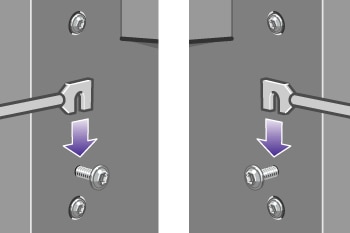
Fix one screw to the inside of the stand’s left leg.Figure : Fix a screw to the left leg

-
Do not fully fit the screw.Figure : The screw protruding

-
Fix one screw to the inside of the stand’s right leg.Figure : Fix a screw to the right leg

-
Do not fully fit the screw.Figure : The screw protruding

-
Lift the supporting framework of the bin into position in front of the printer.Figure : Lifting the bin's frame into position

-
Fix the top arms of the bin to the two screws that you have just fitted.Figure : Fix the top arms of the frame to the stand
-
Fix the lower arms of the bin to the stand using one screw for each leg.Figure : Fix the lower arms of the frame to the stand

-
Now tighten the two top screws.Figure : Tightening the two top screws

-
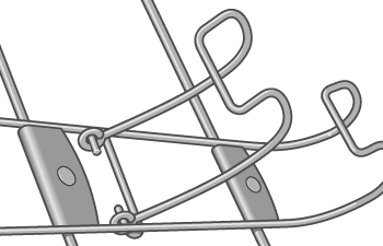
Clip all six loops to the frame of the bin. Locate the loops with rear extensions in positions 2, 4 and 6.Figure : Clip the loops to the frame

-
Secure all six loops to the frame, using two clips on each loop.Figure : Securing the loops to the frame

-
Fit all three mobile stoppers to the three loops as indicated.Figure : Fitting the mobile stoppers

-
Carefully squeeze the mobile stopper and then fit it onto the loop.Figure : Detail of fitting a mobile stopper

-
When the mobile stopper is engaged with the loop, release your grip.Figure : The mobile stopper in place
-
Move the three mobile stoppers into their parked position. These stoppers are used only when printing on sheets of paper less than 900 mm in length (up to A1 size).Figure : Parking a mobile stopper

Switch on for the first time
-
Plug the power cable into the rear of the printer, then plug the other end into the AC power outlet.Figure : Plugging in the power cable

-
Turn the power switch at the rear of the printer to the on position.Figure : Switching on the power

-
If the power light on the front panel remains off, press the Power key to switch on the printer.Figure : Pressing the Power button on the front panel

-
Wait until you see this front panel message. Highlight your language on the front panel using the Up and Down keys. Press the Select key.Figure : The language selection page

-
The front panel will now display how to install the ink supplies.Figure : Ink cartridge installation

Install ink cartridges
-
Remove the printheads, printhead cleaners and ink cartridges from the consumables box.Figure : Unpacking the consumables

-
Find the ink cartridge door, which is on the left side of the printer.Figure : Locating the ink cartridge door

-
Press the ink cartridge door until it clicks.Figure : Pressing the ink cartridge door

-
Open the ink cartridge door.Figure : Opening the ink cartridge door

-
To release the ink cartridge drawer, pull the blue handle down.Figure : Releasing the ink cartridge drawer

-
Slide the ink cartridge drawer out.Figure : Sliding the ink cartridge drawer out

-
Place the ink cartridge onto the ink cartridge drawer.
note:
There are marks on the drawer showing the correct location.Figure : Placing the cartridge on the drawer
-
Position the ink cartridge at the rear of the drawer as indicated.Figure : Positioning the cartridge

-
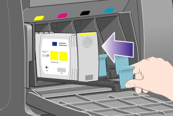
Push the ink cartridge drawer back into the printer until it locks into position.Figure : Pushing the drawer back in
-
Install the other three ink cartridges in the same way.Figure : Installing the other cartridges

-
Close the ink cartridge door (push it until it clicks shut).Figure : Closing the ink cartridge door

-
Wait (about a minute) until you see this front panel message.Figure : Open window to access printheads

Remove the setup printheads
-
Open the printer window.Figure : Opening the window

-
Remove the packing tape that is holding down the printhead carriage latch.Figure : Removing the carriage tape

-
Pull up and release the latch on top of the carriage.Figure : Releasing the carriage latch

-
Lift up the cover. This will give you access to the setup printheads.Figure : Lifting the carriage cover

-
Before removing the setup printheads, look at the window on top of each one and check that the printhead contains ink. If it does not, contact your customer service representative.Figure : Checking for ink

-
To remove a setup printhead, lift up the blue handle.Figure : Removing a setup printhead

-
Using the blue handle, gently disengage the setup printhead from the carriage.Figure : Lifting a setup printhead

-
Lift the setup printhead until it is released from the carriage. Then remove the other setup printheads.Figure : Completing removal of setup printheads

Install the printheads
-
Remove the blue protective cap and the clear protective tape from the printhead.Figure : Removing printhead cap and tape

-
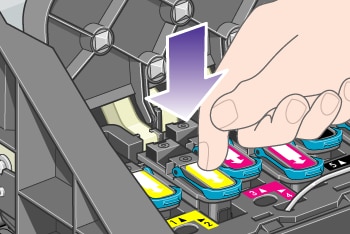
Lower all the printheads vertically into their correct positions.Figure : Lowering the printheads

-
Seat the printheads slowly and carefully.Figure : Seating the printheads (1)

-
Make sure the printheads are correctly seated. When all the printheads are installed, the front panel prompts, “Close printhead cover and window”.Figure : Seating the printheads (2)
-
Close the carriage cover.Figure : Closing the carriage cover

-
Make sure the latch engages correctly.Figure : Engaging the latch

-
Close the printer window.Figure : Closing the window

-
Please wait (about a minute) while the printer checks the printheads.
Install the printhead cleaners
-
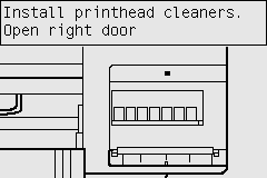
Wait until you see this front panel message.Figure : Install printhead cleaners
-
Press the printhead cleaner door, which is on the right side of the printer.Figure : Pressing the printhead cleaner door

-
Open the printhead cleaner door.Figure : Opening the printhead cleaner door

-
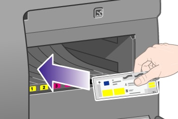
Insert the printhead cleaner into the slot of the correct color.Figure : Inserting the printhead cleaner
-
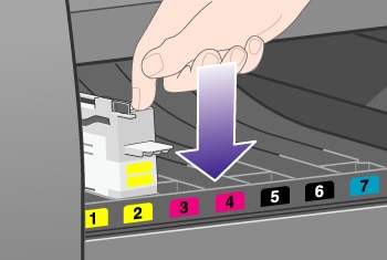
Push the printhead cleaner in and down until it clicks into place.Figure : Engaging the printhead cleaner
-
Insert the other seven printhead cleaners into the correct slots.Figure : Inserting the other printhead cleaners

-
Close the printhead cleaner door.Figure : Closing the printhead cleaner door

-
Wait until you see this front panel message, then press the Select key.Figure : Ready for paper

Load a roll of paper onto the spindle
-
Lower the spindle lever.Figure : Lowering the spindle lever

-
Remove the right-hand end of the spindle (1) from the printer, then move it to the right in order to extract the other end (2). Do not insert your fingers into the spindle supports during the removal process.Figure : Removing the spindle

-
Remove the blue paper stop (1) from the left-hand end of the spindle. Keep the spindle horizontal.Figure : Removing the stop from the spindle

-
Slide the roll of paper onto the spindle. Make sure the paper is oriented exactly as shown.
note:
There is also a label on the spindle showing the correct orientation.Figure : Sliding the roll onto the spindle
-
Put the blue paper stop onto the spindle and push it on as far as it will go without using excessive force.Figure : Putting the stop back on the spindle

-
Make sure the stop is seated correctly.Figure : Seating the stop

-
With the blue paper stop on the left, slide the spindle into the printer. The spindle lever will drop down automatically as you insert the spindle.Figure : Sliding the spindle into the printer

-
When you meet resistance, lift the spindle lever to seat the spindle properly.Figure : Lifting the spindle lever

-
The spindle lever will be in the horizontal position when the spindle has been correctly inserted.Figure : Correct spindle lever position

Load the paper into the printer
-
At the front panel, highlight the
 icon and press the Select key.
Figure : Ready for paper
icon and press the Select key.
Figure : Ready for paper
-
Highlight Paper load and press the Select key.Figure : Paper menu

-
Highlight Load roll and press the Select key.Figure : Roll menu

-
Highlight the paper type you have loaded and press the Select key.Figure : Paper type menu

-
Select the roll length if known.Figure : Selecting the roll length

-
Wait until you see the 'Open window' message.Figure : Open window

-
Open the printer window.Figure : Opening the window

-
Lift the paper load lever.Figure : Lifting the paper load lever

-
Pull out approximately 1 m (3 ft) of the roll.Figure : Pulling out the paper

-
Insert the edge of the roll above the black roller.Figure : Inserting the paper

warning:
Take care not to touch the rubber wheels on the platen while loading paper: they may rotate and trap skin, hair or clothing. -
Wait until the paper emerges from the printer as shown below.Figure : Paper emerging from the printer
-
Make sure the paper is aligned with the blue line and half-circle on the platen.Figure : Aligning the paper

-
Lower the paper load lever.Figure : Lowering the paper load lever

-
You should see the front panel message below.Figure : Wind excess paper onto roll

-
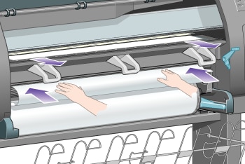
Using the stops, carefully wind the excess paper back onto the spindle.Figure : Rewinding the paper

-
Close the printer window.Figure : Close the window

-
The printer will adjust the paper by winding it back and forth, after which you can expect the front panel message below.Figure : Wind excess paper onto roll

-
Using the stops, carefully wind the excess paper back onto the spindle.Figure : Rewinding the paper
-
The printer will automatically perform printhead alignment and a color calibration for the paper type that you have loaded. During this process the printer will advance the paper by up to 3 m (≈10 ft) before printing. Please do not try to stop the paper advance; it is necessary to ensure a successful printhead alignment. The whole alignment and calibration process will take about twenty minutes; while it is going on, you can start connecting the printer.
Connect the printer
-
Your printer can be connected to a computer directly or to one or more computers via a network.Figure : Ways of connecting your printer
 (1) PC, Macintosh or workstation(2) Printer(3) Server(4) PC, Macintosh or workstation
 -
Locate the area at the back of the printer where you can connect the printer to your computer or network, or install an optional accessory.Figure : Where to connect your printer

-
A Gigabit Ethernet socket is provided for connection to a network.Figure : Gigabit Ethernet socket

-
Two FireWire sockets are provided for direct connection to computers. One of these sockets can also be used to connect the HP Designjet 4520 Scanner.Figure : FireWire sockets

note:
A FireWire cable is not provided with the printer. Any cable recommended by the 1394 Trade Association may be used. -
A larger socket is provided to connect an optional accessory.
caution:
Do not attempt to use this socket for any other purpose.Figure : Accessory socket
-
Pass the network cable through the hook at the rear of the printer.Figure : Network cable hook

Install accessories
There are various optional accessories that you can buy and install at any time during the life of your printer. The physical installation of each accessory is graphically illustrated on the poster provided with the accessory (except in the case of the Jetdirect print server; see below). Here are some further steps to follow after completing the physical installation process.
USB 2.0 socket
To check that the USB 2.0 socket has been correctly installed, go to the front panel and select the  icon, then I/O setup > USB > View information.
icon, then I/O setup > USB > View information.
Figure : I/O setup > USB

The front panel will reveal whether the socket is Installed or Not installed.
Please follow the appropriate instructions to connect the printer to your computer:
-
Connect directly to a computer (Windows)
-
Connect directly to a computer (Mac OS X)
You can plug in your USB cable as illustrated below.
Figure : USB 2.0 socket

Jetdirect print server
To install the Jetdirect card:
-
Go to the rear of the printer and remove a small cover plate secured by two screws near the left-hand side.Figure : Removing the screws
 Figure : Removing the cover plate
-
Insert the Jetdirect card and secure it with the screws that accompany the card.Figure : Inserting the Jetdirect card
 Figure : Securing the card to the printer
-
Save the cover plate and screws in case you decide to remove the Jetdirect card later.
To check that the card has been correctly installed, go to the front panel and select the icon, then I/O setup > Jetdirect EIO > View information.
icon, then I/O setup > Jetdirect EIO > View information.
Figure : I/O setup > Jetdirect EIO

The front panel will reveal whether the print server is Installed or Not installed.
Please follow the appropriate instructions to connect the printer to your network:
-
Connect to a network (Windows)
-
Connect to a network (Mac OS X)
You can plug in your network cable as illustrated below.
Figure : Jetdirect print server socket

Memory expansion card
To check that the 512 MB memory expansion card has been correctly installed, go to the front panel and select the icon, then View printer information. The front panel will display various items of information about the printer, including Memory.
icon, then View printer information. The front panel will display various items of information about the printer, including Memory.
Figure : Show printer information

If the memory size is now shown as 896 MB, your memory expansion card has been correctly installed.
Enter a topic to search our knowledge library
What can we help you with?

Need Help?