The scanner's operator panel is divided into 2 main areas: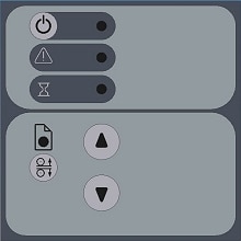
-
Scanner control area with the power button and its power indicator light, wait light, and diagnostics light.
-
Paper control area with the paper ready light, Automatic Thickness Adjustment Control button, and 2 paper feed (arrow) buttons.
Below are the panel's different light patterns and what they indicate regarding scanner operation.
Scanner control area
Turn the scanner power on – First Time – Hard Power on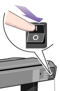
At back of the scanner, plug in the power cable and flip the outlet switch on. The scanner starts the self-test procedure which starts with the Init Sequence.
Init Sequence
(startup phase 1)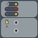
When you invoke Hard Power On by turning scanner power on from the outlet at the back, the scanner runs it's initialization sequence. All the LEDs are lighted as shown above.
Panel input is disabled and you cannot begin scanning.
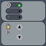
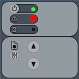
note:When you power up through Soft Power On, by pressing the power key (from red to green) this initialization sequence is skipped and the scanner goes directly to Self-Adjustment (startup-phase 3) as described below.End of Init sequence (startup – phase 2)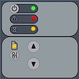 Towards the end of Init Sequence, the Power LED will change to green while the other LEDs remain unchanged (lighted) as shown above. From here the scanner moves on to Self Adjustment (startup phase 3).Soft Power ON and OFF- Turn power ON/OFF with power key –normal use (with outlet switch always ON)
 With the outlet switch always on, use the Operator’s panel Power key to control scanner power. Hold down on the power key to toggle power off/on. This is called Soft Power OFF/ON mode.The power LED lights green when the scanner is on and red when power is OFF. When you turn the scanner on in this manner, it starts in Self-Adjustment mode (startup phase 3) as described below.When in the power off/on mode, the scanner can automatically be powered up and down by WIDEsystem’s timer.Self-Adjustment (startup –phase 3)
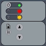
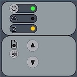 If you used Hard Power On at completion of the Init Sequence, the power LED (green), and the Wait LED (yellow) remain lighted while the others LEDs turn off. This indicates that the scanner is running its Self-Adjustment of light profiles, stitching and black/white points.If you used Soft Power On, the power LED turns to green and the Wait LED is turns on yellow while others LEDs are off. This indicates that the scanner is running its Self-Adjustment with warm-up and adjustment of light profiles, stitching and black/white points.To maintain optimal conditions, the scanner runs new self-adjustment procedures periodically during the day (without lighting the wait LED). If the Wait indicator flashes, the scanner needs to run self-adjustment but cannot (see below).

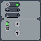
Scanner Ready
(startup – phase 4)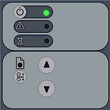
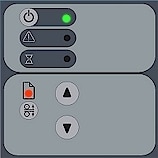
When the Wait LED turns off, and only the Power LED is on and lights green, self-adjustment is completed and the scanner is ready to scan.
Green Power LED flashing
The green power LED will flash just before the scanner automatically powers off because its defined power off time (in WIDEsystem) has been reached.
If you are using the scanner and want to cancel power down, press the power key until the LED stops blinking.
You can at any time disable or change timer settings in WIDEsystem.
Wait LED Flashes - Self-Adjustment required but not possible.
If the Wait LED flashes (and the Diagnostics LED is off) the scanner needs to run Self-Adjustment but cannot. Self-Adjustment is necessary for maintaining optimal and stabile internal conditions.
To solve this, any original in the scanner should be removed, and the insertion slot must be set to the normal position (i.e., not a thick media setting). When Self-Adjustment is again possible, the Wait LED stops flashing, but continues to be on until Self-Adjustment is completed. The scanner should be left alone while Self-adjustment is running.
During Calibration – Wait LED lights
This is normal. The Wait LED is on during Calibration to indicate that the original should not be removed or moved during the Calibration procedure.
All panel input is prevented during basic calibration.

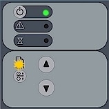
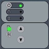
 , you set the scanner in Automatic Thickness Adjustment Control (ATAC) mode. The Paper Ready Key flashes yellow to indicate ATAC mode.