The Latex and LX series of printers use an intermediate tank system to supply ink to the printheads. Ink from the primary ink supply (the external ink cartridge) flows to the intermediate tank, which is then pressurized by air. The air pressure acting on the intermediate tank causes the ink to move through the tube routing system (TRS) in the cable carrier to the carriage, where it replenishes the printheads.
The construction of the intermediate tank is a flexible Mylar bag enclosed in a rigid plastic enclosure. One port in the intermediate tank allows ink to flow in and out of the bag, while a second port allows air to enter the cavity between the bag and the rigid enclosure to apply pressure that pushes ink from the bag into the rest of the ink delivery system. Near the ink and air ports are two electrical contacts separated by a gap. If ink (or any other conductive liquid) enters the area of the contacts, the gap is closed by the ink and the broken bag sensor is activated. The resulting 28.xy:11 error code for the affected intermediate tank is displayed on the front panel, where "xy" is replaced by a number that indicates the tank in question.
Continue with the rest of this document to identify and resolve a broken bag failure. In some cases, depending on the nature and magnitude of the bag break, ink can flow into the air pressure tube, in which case the tube must be cleaned or replaced in addition to replacing the affected intermediate tank. Following the cause identification and correction of the problem, reset the error as described in the concluding section. If at any time end user encounter something unexpected or have additional questions or concerns, contact an authorized HP reseller or the regional HP Customer Care Center.
NOTE:The following procedures involve enabling Diagnostic Mode on the printer. Diagnostic Mode is a special mode that enables menu options specific to troubleshooting and service. Readers of this document and printer operators are strongly cautioned not to attempt to use any Diagnostic menu items that are not specifically recommended by HP and/or that are not fully understood by the person operating the front panel. When any recommended use of Diagnostic mode is completed, restart the printer to exit Diagnostic mode and resume normal operation mode.
Check the status of the broken bag detectors
1. To check the status of the broken bag detectors, the printer must be started in Diagnostic mode. To start in Diagnostic mode, press and hold the Cancel button and the Down Arrow, then press and hold the Power button. Continue to press all three buttons. The LED indicator on the front panel will be steady-on red, then steady-on green, and then finally start blinking green. When the LED begins blinking green, release all three buttons. See Figure 1.

Figure 1 Front panel key combination to start in Diagnostic mode
1 – Cancel button. Press and hold
2 – Down arrow button. Press and hold
3 – Power button. Press and hold
4 – LED. When LED changes from steady-on green to blinking green, release all three buttons
2. With the printer in Diagnostic mode, use the front panel keys to navigate to
4.15.10 Int T Front Brk Bag or
4.15.11 Int T Rear Brk Bag, depending on which color is presenting the original 28.xy:11 error code. See Figure 2.

Figure 2 4.15.10 Int T Front Brk Bag
If the front panel display for
4.15.10 Int T Front Brk Bag or
4.15.11 Int T Rear Brk Bag shows that any one of the bags is not "OK", then that tank must be removed and inspected for possible breakage. To access the intermediate tanks, one or more of the ISM (ink system module) enclosures must be removed. See figures 3 and 4.

Figure 3 Input-side or back ISM enclosure removal. Remove this panel for access to magenta, light magenta, and light cyan components
1 – Torx T30 fastener (six locations)
2 – Enclosure panel
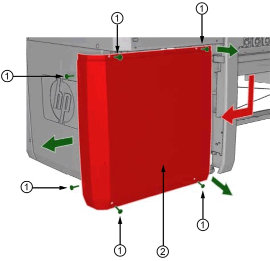
Figure 4 Output-side or front ISM enclosure removal. Remove this panel for access to black, cyan, and yellow components
1 – Torx T30 fastener (six locations)
2 – Enclosure panel
With the panel(s) removed, the intermediate tanks are visible. See Figure 5 for an example.

Figure 5 Front intermediate tanks
Note that there is some discrepancy between the front panel software numbers for the intermediate tanks and how the physical tanks themselves are labeled. In Figure 5, the physical intermediate tanks for black are labeled “11” and “12”, while in Figure 2 the front panel display for
4.15.10 Int T Front Brk Bag indicates the two black tanks as "00" and "01", and so on throughout the colors. Fortunately this discrepancy is consistent, and it should not be too difficult to determine which physical tank is being referred to by the front panel. Note also that the middle number of the error code itself ("28.11:11", "28.12:11" etc.) does correspond to how the tanks are physically labeled.
3. Locate the intermediate tank that corresponds to the tank flagged on the front panel and remove it by gently pressing the tank back into the machine and lifting up slightly on the front, then pulling the entire tank from its slot. Be prepared with paper towels or other absorbents to catch any leaking ink if the bag is indeed broken.
4. If the bag is broken, it should be obvious and liquid ink will be visible in the connecting end of the tank. Set the broken tank aside for now and dispose of the remaining ink contents in accordance with local regulations.
5. Using a flashlight, inspect the internal area of the intermediate tank bay. Any ink in the bay will need to be cleaned up in order to reset the error. See Figure 6.

Figure 6 Connections inside the intermediate tank bay
1 – Electrical contacts, including the broken bag sensor contacts
2 – Ink connection
3 – Air pressure connection
The electrical contacts in particular must be thoroughly cleaned using isopropyl alcohol (IPA). If the connections cannot be easily reached, it is possible to remove the rectangular housing for all the intermediate tanks and expose the connections directly.
Caution: if the tank housing is to be removed, turn off the printer to avoid possible damage to electronic parts of the ISM during the procedure. When complete, the printer must be started in Diagnostic mode again.
To remove the tank housing, remove all of the intermediate tanks and store them upright on end, not horizontally.
NOTE:Do not attempt to remove the housing with the intermediate tanks in place.
On the "back" side of the tank housing assembly, i.e., the side that is most interior to the printer, opposite of the open side where the tanks are inserted, there are three blue latches. Rotate these latches, and then lift the housing away from the printer. See figures 7, 8, and 9.

Figure 7 Blue latches securing intermediate tank housing. This view is from the outside end of the ISM looking at the back-color intermediate tank housing for magenta, light magenta, and light cyan. For orientation, an ink pressure sensor board can be seen at the left foreground.
1 – Latches (3 places)
2 – Tank housing
3 – Data cable
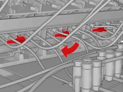
Figure 8 Rotate the latches

Figure 9 Remove the housing from the printer. It may be necessary to wiggle the housing in order to free it for removal.
Be careful of the blue data cable (item 3 in Figure 7) that is still attached to the tank housing. Set the tank housing aside and clean the contacts shown in Figure 6. When complete, reassemble the tank housing into the printer and close the latches. Reinstall the other intermediate tanks removed earlier.
6. If the intermediate tank identified by the front panel does appear to be broken, replace it using the following spare part number:
Click here to view the spare part number for "Intermediate tank broken bag repair kit".
If the original air tube in the printer was contaminated by ink, it must be cleaned or replaced. See the following section on cleaning or replacing the air tube. When all repairs are complete, proceed to the concluding section on resetting the 28.xy:11 error.
7. If the intermediate tank identified by the front panel does
not appear to be broken, i.e., the 28.xy:11 was a false alarm or was caused by some liquid residue leftover from a previous broken bag event, etc., ensure that the tank contacts are clean and reinstall the tank into the printer. Proceed to the concluding section on resetting the 28.xy:11 error.
Clean or replace the air tube
HP spare part
Intermediate Tank Bag provides the necessary tubing and related components to replace the air tube from the intermediate tank to the air pressure bottle. If the air tube is contaminated with ink, follow the steps below to clean or replace it.
1. Locate the air tube related to the position of the original broken bag issue.
2. Pull the air tube from the intermediate tank housing. Be prepared with paper towels or other absorbents to catch any ink that drips from the tube.
3. Follow the air tube to the air pressure bottle located in the center area of the ISM.
4. Pull the air tube from the top of the bottle.
5. Use compressed air and/or water to clean out any ink from the tube. Ensure that the tube is completely dry, and then reinstall it onto the air pressure bottle and onto the intermediate tank housing.
6. If the original tube cannot be adequately cleaned, use the replacement tube segment and/or tube joiner included in the following spare part number to install the replacement tube.
Click here to view the spare part number for "Intermediate tank broken bag repair kit".
If any ink escaped onto the lower ISM tray during the tube change, clean it up using paper towels or other absorbents.
The associated air pressure bottle may also have been contaminated with ink, in which case it must also be removed and cleaned. When removing the bottle, hold the cap with air tubes steady and rotate the bottle to unscrew it. Reinstall the bottle using the same technique. In the event of a severe contamination problem with the bottle and/or cap, replace it using the following spare part number which provides a replacement bottle, cap, associated tubing, and tube joiners.
Click here to view the spare part number for "ISM air circuit module".
Reset the 28.xy:11 error
When a 28.xy:11 error occurs, it sets a software flag that must be reset in order to clear the error. When the root cause of the error has been corrected, reset the flag by performing the following steps:
1. Start the printer in Diagnostic mode as described in the preceding section. See figure 1, above.
2. With the printer in Diagnostic mode, use the front panel keys to navigate to 4.4 IT broken bag recovery.
3. Follow the on-screen prompts to clear the error condition.
4. If a new, empty intermediate tank has been installed, continue with the process to fill the new tank. If the tank is not new or empty, e.g., end user are troubleshooting a phantom error message, end user may press cancel to exit the procedure.
5. Ensure that the ink cartridge for the affected color has at least 30% volume remaining. If the volume is less than 30% on the current ink cartridge, install a new cartridge to complete the recovery, and then reinstall the previous cartridge. If the current cartridge has less than 30% remaining, the front panel may show a message indicating that the cartridges are not ready, and will not allow the procedure to continue.
6. Follow the on-screen prompts to fill the new intermediate tank.
7. When the procedure is complete, turn off the printer.
8. Restart the printer normally and observe for any recurrence of the original 28.xy:11 error. If the error occurs, the troubleshooting of the error was not successful. Recheck the tank housing area for any ink residue that was not cleaned up and re-try.
9. If the error persists or additional assistance is needed, contact an authorized HP reseller or HP regional Care Center.
Additional note concerning spare parts
As noted earlier in this document, HP spare part
Intermediate Tank Bag provides all the necessary materials to replace one intermediate tank and the related air tube for that tank. HP spare part
Intermediate Tanks provides a complete set of 12 replacement tanks, but it does not include the air tubing and associated hardware. For this reason Q6702-60432 is not normally used to replace tanks that have failed due to broken bags even when multiple bags are affected.
NOTE: Part numbers can change without notice, please verify the part numbers from HP PartSurfer website. Click here to view HP PartSurfer website.
