This document applies to Sprout by HP.

warning:Make sure the computer is disconnected from power before starting.
caution:This product contains components that can be damaged by electrostatic discharge (ESD). To reduce the chance of ESD damage, work over a noncarpeted floor, use a static dissipative work surface (such as a conductive foam pad), and wear an ESD wrist strap connected to a grounded surface.
caution:Procedures in this document are provided by HP for qualified service agents and as a courtesy to its customers. Servicing internal components increases the risk of damaging the computer which might not be covered under warranty. Understand the risk and refer to the product's warranty before attempting to service the computer.
note:For best quality on dial-up connections, wait until the video has fully loaded before viewing.

|
Step 1
First, remove the touch mat, the right rear cover, the left rear cover, the column assembly, and the top rear cover.
For detailed instructions to remove these parts, see the HP support document, Remove and Replace the top rear cover for HP Sprout by HP.
|

|
|
Step 2
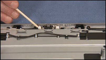
Now remove the microphone assembly.
Detach the motherboard connector from the motherboard side edge of the microphone board.
|
|
|
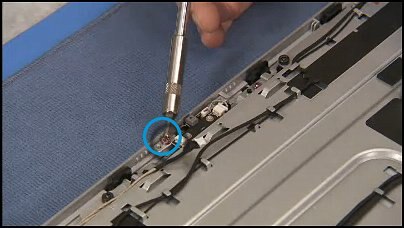
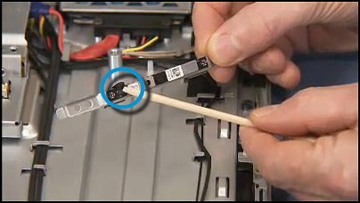
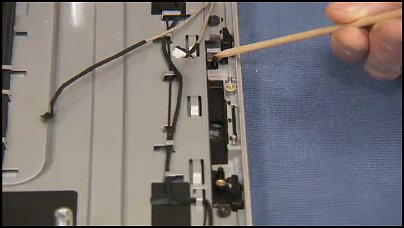
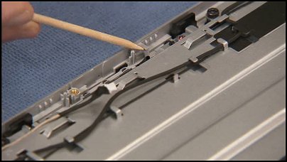
Step 3
Detach the silver pink torx head screw that secures the microphone bracket to the top of the computer.
|
|
|
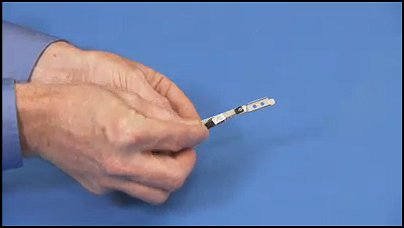
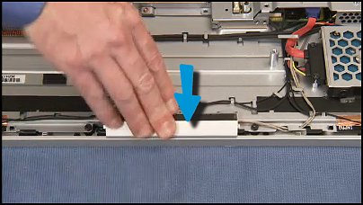
Step 4
Pull the microphones bracket assembly out of the computer.
|
|
|
Step 5
Now, to remove the webcam. remove the pink torx head screw that secures the webcam assembly to the computer.
|

|
|
Step 6
Pull up on the edges of the webcam bracket...
|
|
|
...and partially pull the webcam assembly out of the computer, placing it to the side.
|

|
|
Step 7
Detach the connector from the webcam...
|
|
|
...and remove it from the cable guides on the webcam bracket, in order to fully remove the webcam assembly from the computer.
|

|
|
Step 8
Carefully pry the webcam off of its bracket.
|
|
|
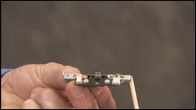
Step 1
Find the two small holes on the webcam...
|

|
|
... that align over two small locator pegs on the webcam bracket.
|

|
|
Step 2
To replace the webcam board to the bracket place the adhesive side of the board on the bracket, aligning the holes over their pegs.
|

|
|
Step 3
Find the two holes on the webcam bracket...
|
|
|
... that align over two alignment pegs on the front bezel.
|
|
|
Step 4
Find the right edge of the webcam bracket...
|

|
|
...that fits under a small lip at the top of the computer.
|
|
|
Step 5
To replace the webcam bracket, first align the webcam connector into its guides on the bracket...
|

|
|
... and reattach the webcam connector to the webcam board.
|
|
|
Step 6
Align the edge of the bracket under its lip...
|

|
|
...and then press the holes of the bracket over their alignment pegs on the front bezel.
|

|
|
Step 7
Replace the single pink torx head screw to secure the webcam bracket in the computer.
|
|
|
Step 8
Now, to replace the microphone, find the two small holes on the top edge of the microphone bracket...
|
|
|
... that fit over alignment pegs at the top of the unit.
|
|
|
Step 9
Find the top edge of the bracket...
|
|
|
...that fits under a small lip on the front bezel.
|
|
|
Step 10
To replace the microphone bracket, tip the left edge of the bracket under its lip on the front bezel, then press the holes on the microphone bracket.
|
|
|
Step 11
Replace the pink torx head screw to secure the microphone bracket to the top of the computer.
|
|
|
Step 12
Replace the motherboard connector to the side edge of the microphone board.
|
|
|
Step 13
Replace the touch mat, the right rear cover, the left rear cover, the column assembly, and the top rear cover.
For detailed instructions to replace these parts, see the HP support document, Remove and Replace the top rear cover for HP Sprout by HP.
|
|
