This document is intended as a basic troubleshooting guide for all HP Designjet Copier products. Dust, dirt, or scratches on the glass plate or on the white background of the guide plate, can cause a wide variety of errors, calibration failures, and scan quality issues. For example, users may see a wash of color or overcast in printed images or they may complain of vertical lines that appear embedded over their original image. It is recommended that the steps in this document be followed in the order listed.
-
Gather information about the issue. Look at the "Wide System" for any error codes.
-
Make sure the White background plate is perfectly clean and not damaged. Make sure the glass plate is also perfectly clean on both sides and free of smudges or finger prints. Do a sample scan using the middle of the scanner, look at color and stitching. Note what is being seen, does it look correct?
-
If the scan is all black, check that the scanner lamp is on (the lamp will turn on shortly after the scanner is powered up). If the scanner light is out then contact HP Support. Otherwise, continue with the remaining steps.
-
If the scan is half black and half correct, then contact HP Support. Otherwise, continue with the remaining steps.
-
-
Check the hours on the lamp.
-
Go into "Scan Test 6" #1 system information
-
Firmware older than 2.6.4 did not display the preventative maintenance message, if the hours are over 4000 then stitching errors could occur, it is strongly recommended that the lamp be replaced.
-
-
Run "Scan Test 6" #20 (Noise Test). This test will show you where the scanner is seeing marks on the glass in RGB (red, green and blue). These marks may be dirt, dust or scratches on either side of the glass, or dirt, dust or scratches on the white background..
note:
The calibration sheet must be loaded to perform this test.Figure : Noise test, red values Figure : Noise test, blue values
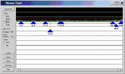 Figure : Noise test, green values
 When looking at the Noise Test make sure that you verify if INCH (inches) or CM (centimeters) is being used. The numbers are where the dirt or scratch is located. For example, the 13.5 pointer means that there is a mark that the noise test is capturing and it is 13.5 inches from the right side. Make sure you check ALL color values (red, green and blue). You do not need to look at Gray.
 -
If you see a lot of arrows in the Noise Test, then clean the scanner, especially if the marks are around the 21-inch area. Any marks in that area may interfere with the stitching wire image and may cause stitching errors.
-
Clean the glass on both sides using a film free cleaner.
caution:
Do not use abrasives, acetone, benzene, or fluids that contain these chemicals. Do not spray liquids directly onto the scanner glass plate or anywhere else in the scanner. Clean the glass with a lint-free cloth and a mild, streak-free, glass cleaner. Dry the glass completely using a separate clean, dry lint-free cloth like the one provided with the maintenance kit. -
Clean the guide plate and ensure that its surface is completely white. If the guide plate is damaged, then the white background needs to be replaced.
-
Be sure that the guide plate is all the way down, check to make certain that the stand off (See Figure 4, Callout 1) on the height indicator of the guide plate is at "2" on both ends. If it is not you can get camera adjust errors or stitching errors.Figure : Height Indicator of the guide plate, showing the "stand off" set at "2"

-
Verify that the stitching wire is in place.
-
Refresh the white background calibration, it must be power-cycled.
note:
All scanner calibrations are based on the white calibration which is done only when the scanner is powered on, If a bad white calibration is stored, all other cals on the scanner may be thrown off and stored incorrectly until the scanner is powered off and then on again. -
Inspect the glass and guide plate for ANY scratches or marks.
-
Run the Noise Test again.
-
Once the Noise Test looks clean, continue with the remaining steps.
-
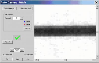
Close the Noise Test and run Test Number 11, Stitching and Vertical Alignment.
note:
The calibration sheet must be loaded to perform this test.Figure : Stitching and Vertical Alignment test
-
Select the Vertical Alignment button and watch the touch screen very closely. The scanner should AUTOMATICALLY adjust the camera and you should be able to see the changes on the screen. When you see a green checkmark, the Vertical alignment portion of the test is complete.Figure : Vertical alignment test
-
Now select Horizontal Stitch. The scanner will look at the scan sheet and if/when all is well, you will see a green checkmark, click Exit.Figure : Horizontal Stitch test

-
Close out of Scan Test 6.It will take a couple of minutes for the scanner to go back to a ready mode.
-
Run the Scanner Maintenance (Start, Programs, Scanner maintenance).
-
Run a test scan (Step 2 above), and compare the results.
If the steps in this document do not resolve the errors, contact HP Support.
